EN
35
Installation
www.bora.com
Shut off the gas supply if you determine that gas is
escaping and ventilate the room.
Seal the point from which the gas is leaking.
Re-check all connections and the gas connection.
Repeat the leak test until all connections are tight.
Create a leak test record and give this to the user.
Switch on the main switch/automatic circuit breaker.
Start up the system (see the Operation section)
Check all the functions of the cooktop extractor and
cooktop are working correctly.
Check the burner flame is working correctly,
particularly when the cooktop extractor is in use.
4.14.3 Changing the gas type
INFO
The burner nozzles, gas type and pressure may only
be changed by a certified engineer or BORA service
technician. He/she also assumes responsibility for
the proper gas installation and commissioning.
Switch all appliances off.
Close the gas supply to the gas supply pipe.
Switch off the main switch/automatic circuit breaker.
Secure the main switch/automatic circuit breaker
against being switched back on without permission.
Make sure the power to the appliance is disconnected.
Changing the gas burner nozzle in the gas
burner
INFO
The nozzles regulate the maximum gas throughflow
for each burner and gas type/pressure.
INFO The gas cooktop is set by default to natural gas
G20/20mbar (pre-assembled).
INFO Use only stamped and approved nozzles.
The stamp on the nozzles corresponds to the values in
the nozzle table and can be found either on the top or
side of the nozzles.
EU
Gas type/
gas pressure mbar
Ø SR burner/
normal burner
Ø R burner/
high-power burner
G20/20 104 125
G25/20 110 131
G20/10 122 155
G20/13 115 149
G25/25
G25.3/25
104 131
G20/25 100 119
G30/29
G31/37
69 85
G30/50
G30/31 – 50 mbar
62 78
Tab. 4.9 Nozzle table
Total nominal connection values for liquid gas:
Gas type mbar kW g/h m³/h
G30/G31 50 4.90 328 0.129
G30 29 5.00 348 0.137
Tab. 4.10 Liquid gas nominal connection values
Total nominal connection values for natural gas:
Gas type mbar kW m³/h
G20 20 5.00 0.449
G25 25 5.10 0.538
G25.3 25 5.10 0.538
G20 13 5.10 0.486
G25 20 4.80 0.501
Tab. 4.11 Natural gas nominal connection values
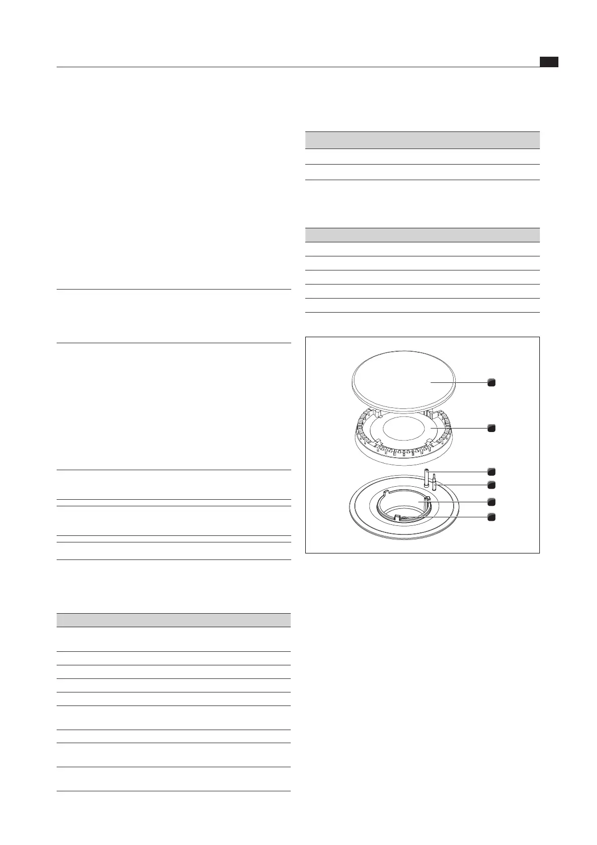
1
2
3
4
5
6
Fig. 4.45 Gas burner structure
[1] Burner cap
[2] Burner head
[3] Electric igniter
[4] Safety thermocouple
[5] Burner housing
[6] Gas burner nozzle
Remove the pan support.
Remove the burner cap [1] from the burner head [2].
Remove the burner head [2] from the gas outlet.