6
WWW.NIKOLAOUTOOLS.GR WWW.NIKOLAOUTOOLS.GR
EN EN
* The manufacturer reserves the right to make minor changes to product
design and technical specicaons without prior noce unless these changes
signicantly aect the performance and safety of the products. The parts
described / illustrated in the pages of the manual that you hold in your hands
may also concern other models of the manufacturer's product line with similar
features and may not be included in the product you just acquired.
* To ensure the safety and reliability of the product and the warranty validity,
all repair, inspecon, repair or replacement work, including maintenance and
special adjustments, must only be carried out by technicians of the authorized
service department of the manufacturer.
* Always use the product with the supplied equipment. Operaon of the product
with non-provided equipment may cause malfuncons or even serious injury or
death. The manufacturer and the importer shall not be liable for injuries and
damages resulng from the use of non-conforming equipment.
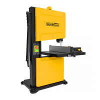
Technical Data
Model BBS2100
Voltage 230 V / 50 hz
Power 350 W S1
No Load Speed 1500 rpm
Blade Length 1400 mm
Max Cung Depth 80 mm
Table Tilt 0 - 45°
Weight 15 kg
SPECIFICATIONS
Main Parts
1 Push sck
2 Housing door
3 Clamping screw
4 Door lock
5 Saw band guard
6 Upper guide
7 Saw table
8 Height adjustment
9 Retaining screw
10 Running wheel adjustment
11 Locking nut
12 Frame
13 Clamping plate
14 Mains connecon cable
15 Handle screw
16 Angle scale
17 Locking handle
18 Connecon for dust extracon
19 Device base
20 Transverse stop
21 Parallel guide
22 Table insert
Scope of Delivery
• Bandsaw
• Band saw blade, 140 cm (pre-mounted)
• Saw table
• Push sck
• Parallel guide
• Transverse stop
• 3× Allen key 3, 4, 5 mm
• Instrucon manual
23 Allen key; 3, 4, 5 mm
24 Open-end wrench; 10 mm (not included)
25 Drive wheel
26 Pin (Safety switch)
27 Safety switch
28 Band saw blade
29 Running wheel
30 Reinforcer
31 ON buon I
32 OFF buon O
(Img. D,E)
33 Mounng screw (Rear guide)
34 Mounng screw (lateral guide)
35 Guide pin
36 Guide roller
37 Mounng screw (Guide pin)
(Img. F)
38 Support screw
39 Nut
PREPARATION
Transport
Never use separang guards for liing or transporng.
Lower the upper guide (6) down as far as possible before transport.
Carry the machine with the base (19) in one hand and the frame (12) in the other.
Assembly
The machine is not ready for operaon on delivery. The following steps must be taken before using the machine for the rst me.
Tools required: Hex key (4 mm) (23)
Assemble the saw table
WARNING! Risk of injury due to unintenonal start-up. Do not insert the plug into the outlet unl the device is fully prepared for use.
WARNING! Cung injuries! Wear cut-resistant gloves when working with the saw blade.