Installation, Operation & Application Manual Bosch 3H/2C Touch-TechnologyThermostat | 7
Bosch Thermotechnology Corp. | 08.2016
Data subject to change
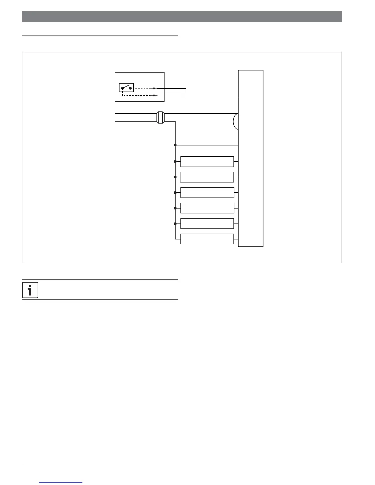
4 Wiring diagram
T
H
E
R
M
O
S
T
A
T
A
RH
RC
C
Y1
W1
O/B
G
W2
Y2
UPM
Transformer
120 VAC
Fan
Heat #2
24 VAC
AUX
Heat #3
Cool/Compressor #1
Cool/Compressor #2
Heat #1/Reversing Valve
OUT
COM
ALR
Figure 2
Factory installed jumper between RH and RC is required.
Thermostat is powered between RH & C.
4.1 Terminal designator descriptions
A – Alarm/display (24 VACinput, switched from RH)
RC, RH – 24 VAC hot
C – 24 VAC common
Y1 – 1st stage cool, 1st stage heat for heat pumps
Y2 – 2nd stage cool for 2-stage or 2-compressor systems. 2nd stage heat
for 2-stage or 2-compressor heat pump systems.
G – Fan
W1/O/B – Configurable
— W1 – 1st stage heat for non-heat pump systems
— O – Cool active reversing valve
— B – Heat active reversing valve
W2 – 2nd stage heat for 1 compressor heat pump and non-heat pump
AUX – 3rd stage heat