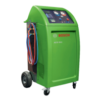
Fig. 2: Rear
1 Service quick-release coupling (high pressure)
2 Service quick-release coupling (low pressure)
3 Service hose (2,5m/5m)1)
4 Service hose mount
5 Rear wheels
6 Master switch
7 Power cord (socket)
1)
Depending on version ordered
3.4 Description of unit
4
6
5
1
2
3
8
7
9
10
12
11
Fig. 1: Front view
1 Valve high pressure (hp)
2 Valve low pressure (lp)
3 Printer
4 Display and control panel
5 Gauge low pressure (lp)
6 Gauge high pressure (hp)
7 Pressure gauge of internal refrigerant cylinder
8 Fresh oil bottle
9 UV dye bottle
10 Used oil bottle
11 Cover
12 Front wheels with locking brake

 Loading...