| 42 | ACS 810 | Product descriptionen
1 689 989 601 2020-12-01| Robert Bosch GmbH
4.4 Description of unit
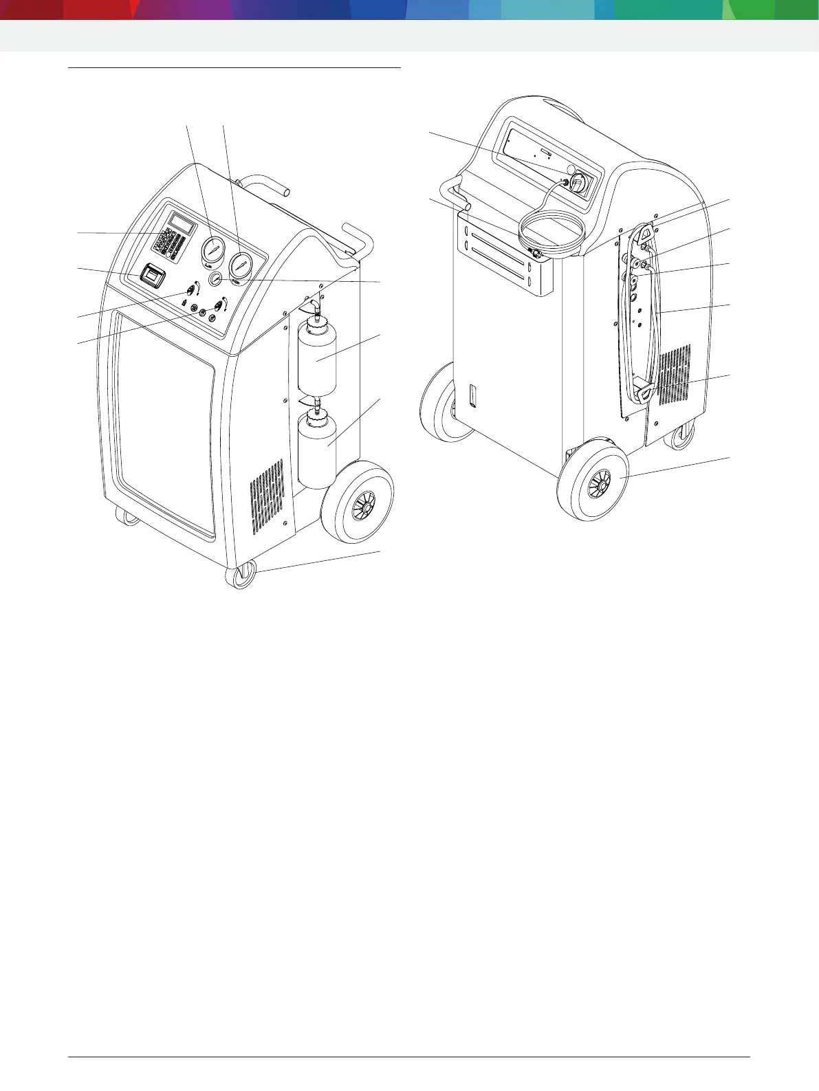
4.4.1 Front view
7
8
9
FV_ACS810
Fig. 1: Front view
1 Valve high pressure (HP)
2 Valve low pressure (LP)
3 Printer
4 Display and control panel
5 Gage low-pressure pressure (LP)
6 Gage high-pressure valve (HP)
7 Pressure gage of internal refrigerant cylinder
8 Fresh oil bottle
9 Used oil bottle
10 Front wheels with locking brake
i The high(6) and low pressure(5) gages show
the current pressure during the air conditioning
service on the vehicle. The small gage(7) is used to
check the bottle pressure in the internal refrigerant
cylinder.
i The two valve settings are labeled as follows:
$ C (closed) = valve is closed
$ O (open) = valve is open
4.4.2 Rear
4
1
2
3
4
5
Fig. 2: Rear
1 Service quick-release coupling (LP)
2 Service quick-release coupling (HP)
3 Service hose (5m)
4 Service hose mount
5 Rear wheels
6 Power cord (socket)
7 Master switch
 Loading...