18 Climate 5000 SCI – 6720887405 (2018/04)
Wiring
8.1 Outdoor Unit Wiring
WARNING
Before performing any electrical or wiring work, turn off the main power
to the system.
1. Prepare the cable for connection.
a. You must first choose the correct cable size before preparing the
cable for connection. Ensure to use H07RN-F cables.
Rated Current of Appliance
(A)
Nominal Cross-Sectional Area
(mm²)
≤6 0.75
6 - 10 1
10 - 16 1.5
16 - 25 2.5
25 - 32 4
32 - 45 6
Table 9. Minimum cross sectional area of power and signal cables
b. Using wire strippers, strip the rubber jacket from both ends of signal
cable to reveal about 150 mm of the wires inside.
c. Strip the insulation from the ends of the wires.
d. Using a wire crimper, crimp u-lugs on the ends of the wires.
NOTE:
While connecting the wires, please strictly follow the wiring diagram
(found inside the electrical box cover).
2. Remove the electric cover of the outdoor unit. If there is no cover
on the outdoor unit, disassemble the bolts from the maintenance
board and remove the protection board. (See Fig. 36)
Cover
Screw
Fig. 36.
3. Connect the u-lugs to the terminals.
Match the wire colours/labels with the labels on the terminal
block, and firmly screw the u-lug of each wire to its corresponding
terminal.
4. Clamp down the cable with designated cable clamp.
5. Insulate unused wires with electrical tape. Keep them away from any
electrical or metal parts.
6. Reinstall the cover of the electric control box.
8.2 Indoor Unit Wiring
1. Prepare the cable for connection
a. Using wire strippers, strip the rubber jacket from both ends of signal
cable to reveal about 150 mm of the wires inside.
b. Strip the insulation from the ends of the wires.
c. Using wire crimper, crimp the u-lugs to the ends of the wires.
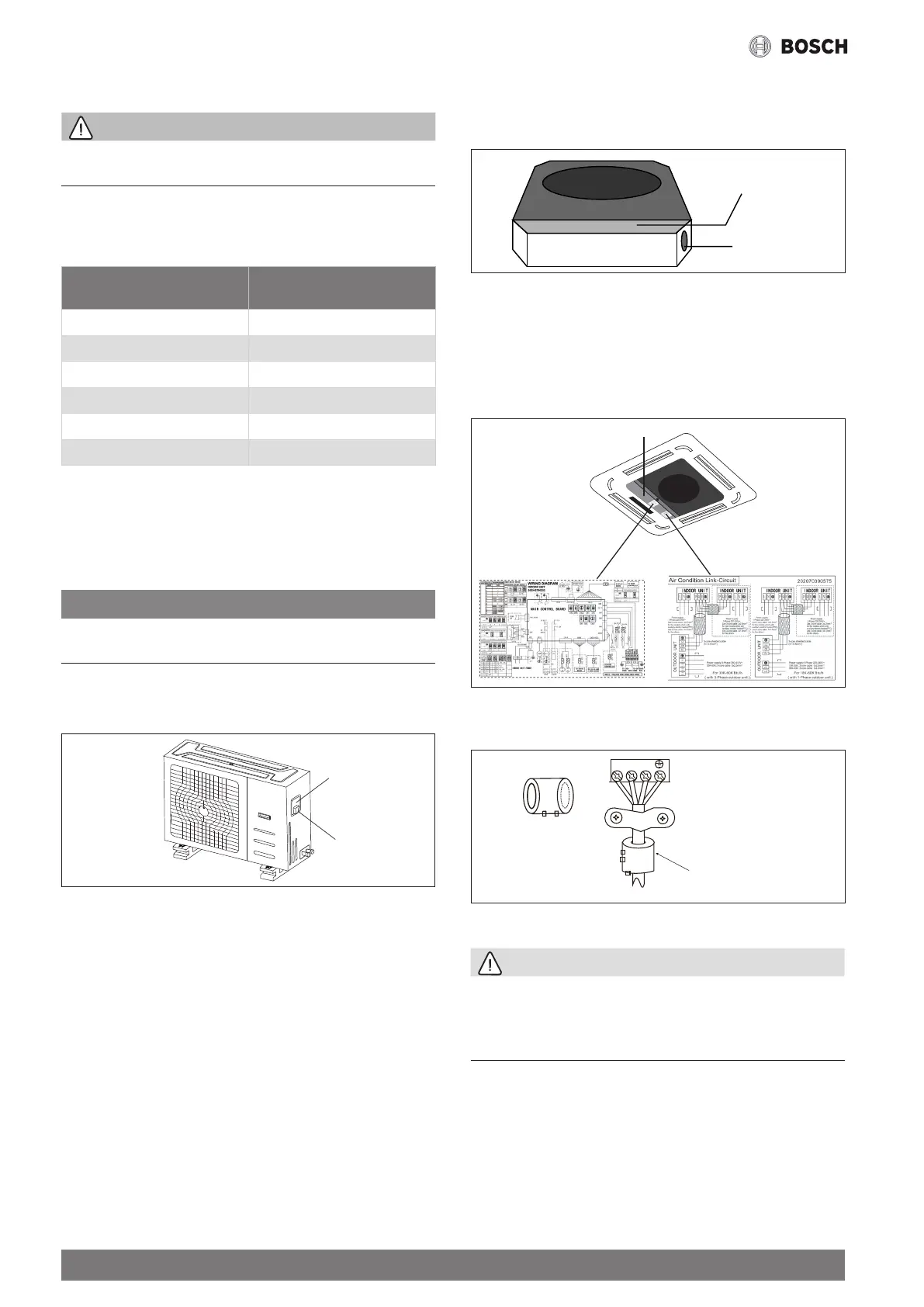
2. Open the front panel of the indoor unit. Using a screwdriver, remove
the cover of the electric control box on your indoor unit.
3. Thread the power cable and the signal cable through the wire outlet.
Wire outlet
Control box
Fig. 37.
4. Connect the u-lugs to the terminals.
Match the wire colors/labels with the labels on the terminal
block, and firmly screw the u-lug of each wire to its corresponding
terminal.
Refer to the Serial Number and Wiring Diagram located on the cover
of the electric control box.
Control box
Fig. 38.
Magnetic ring (if supplied and packed with the accessories)
1 2 3
Pass the belt through the hole
of the magnetic ring to fix it on
the cable
Fig. 39.
CAUTION
• While connecting the wires, please strictly follow the wiring dia-
gram.
• The refrigerant circuit can become very hot. Keep the interconnec-
tion cable away from the copper tube.
5. Clamp down the cable with the designated cable clamp to secure it
in place. The cable should not be loose, and it should not pull on the
u-lugs.
6. Reinstall the electric box cover and the front panel of the indoor unit.