Climate 5000 SCI – 6720887405 (2018/04) 21
Panel Installation
Liquid Side Diameter
Ø 6.35(1/4”) Ø 9.52(3/8”) Ø 12.7(1/2”)
R410A
(Orifice tube in the indoor unit):
(Total pipe length – standard pipe
length) x 30g (0.32 oZ)/m(ft)
(Total pipe length – standard pipe
length) x65g (0.69 oZ)/m(ft)
(Total pipe length – standard pipe
length) x 115g (1.23 oZ)/m(ft)
R410A
(Orifice tube in the outdoor unit):
(Total pipe length – standard pipe
length) x 15g (0.16 oZ)/m(ft)
(Total pipe length – standard pipe
length) x 30g (0.32 oZ)/m(ft)
(Total pipe length – standard pipe
length) x 65g (0.69 oZ)/m(ft)
R32 (Total pipe length – standard pipe
length) x 12g(0.13 oZ)/m(ft)
(Total pipe length – standard pipe
length)x 24g (0.26 oZ)/m(ft)
(Total pipe length – standard pipe
length) x 40g (0.42 oZ)/m(ft)
Table 11.
10 Panel Installation
CAUTION
DO NOT place the panel face down on the floor, against a wall, or on
uneven surfaces.
Step 1: Remove the front grille.
1. Push both of the tabs towards the middle simultaneously to unlock
the hook on the grille.
2. Hold the grille at a 45° angle, lift it up slightly and detach it from the
main body.
Fig. 42.
Step 2: Remove the installation covers at the four corners by sliding
them outwards.
Fig. 43.
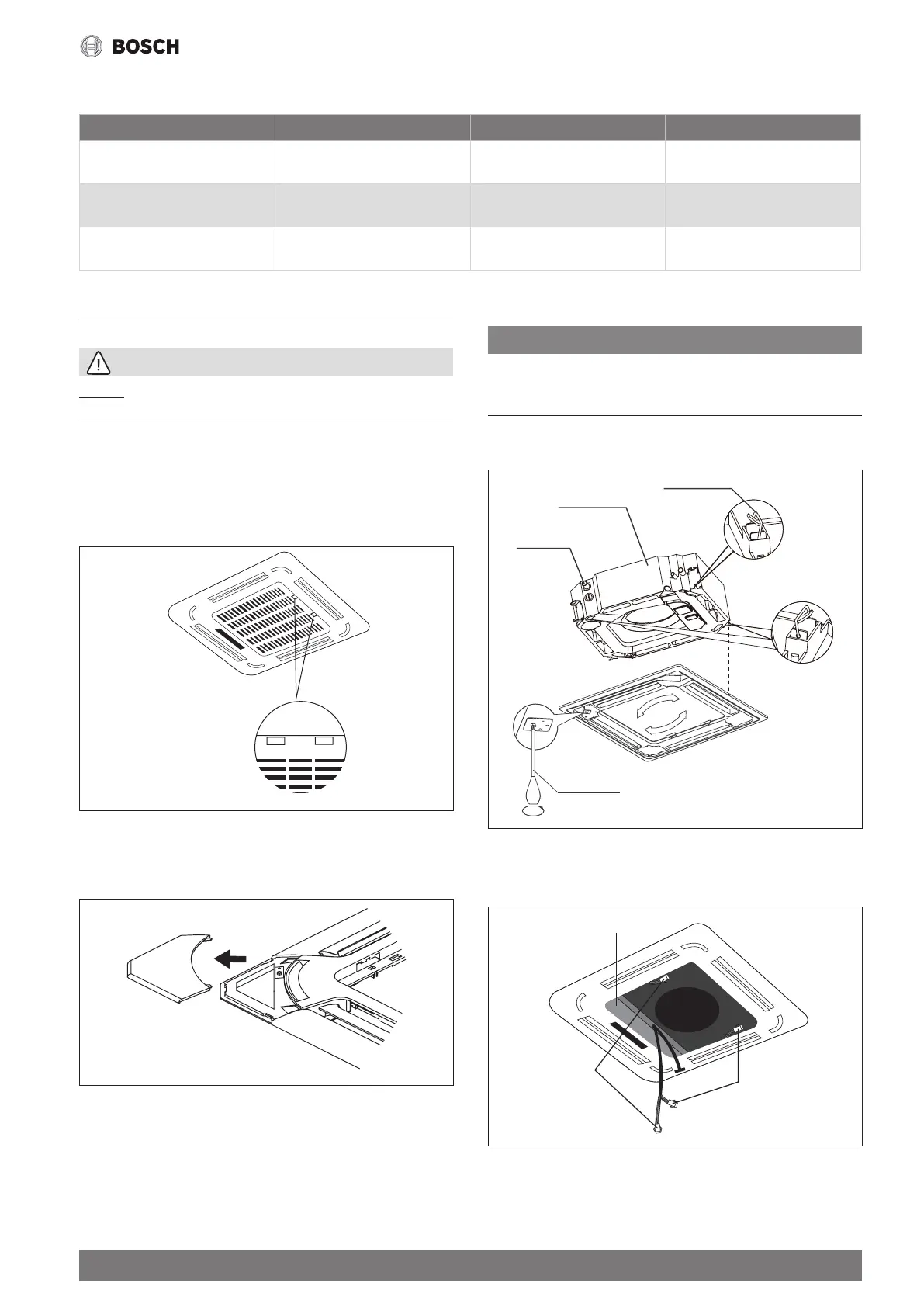
Step 3: Install the panel
Align the front panel to the main body, taking into account the position of
the piping and drain sides. Hang the four latches of the decorative panel
on the hooks of the indoor unit. Tighten the panel hook screws evenly at
the four corners. (See Fig. 44)
NOTE:
Tighten the screws until the thickness of the sponge between the main
body and the panel decreases to 4-6 mm. The edge of the panel should
be in contact with the ceiling well.
Adjust the panel by turning it to the direction of the arrows shown in
Fig.44 so that the ceiling opening is completely covered.
Latch
Piping side
Drain side
Screwdriver
Fig. 44.
1. Connect the two louver motor connectors to the corresponding
wires in the control box.
Control box
Connect to the
louver motor
Connect to the
louver motor
Fig. 45.
2. Remove foam stops from inside the fan.
3. Attach the side of the front grille to the panel.