8 Climate 5000 SCI – 6720887405 (2018/04)
Indoor Unit Installation
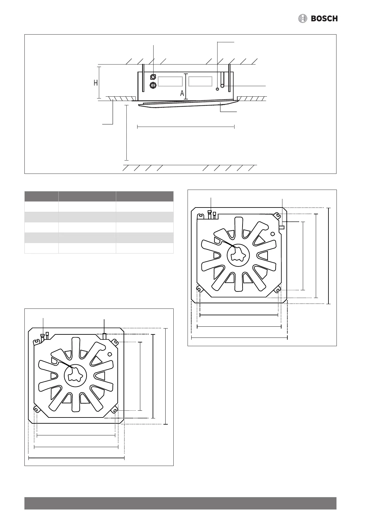
Connecting point of
drain pipe
Ceiling
Front panel
>2.5 m
880 mm (Ceiling hole)
Ground
Ceiling board
Connecting point of refrigerant
pipe (liquid side)
Connecting point of refrigerant
pipe (gas side)
Fig. 2.
MODEL Length of A (mm) Length of H (mm)
18 205 > 235
24 205 > 235
30 205 > 235
30-48 245 > 275
48-60 287 > 317
Table 3. Distance from ceiling relative to height of indoor unit
Step 2: Hang indoor unit.
1. Use the included paper template to cut a rectangular hole in the
ceiling, leaving at least 1 m on all sides. The cut hole size should be
40 mm larger than the body size (See Fig. 3).
Ensure to mark the areas where ceiling hook holes will be drilled.
Refrigerant piping side
780 mm (Suspension bolt)
680 mm (Suspension bolt)
840 mm (Body)
840 mm (Body)
950 mm (Ceiling opening)
950 mm (Ceiling opening)
18-48K ceiling hole size
Drain hose side
Fig. 3.
Refrigerant piping side
840 mm (Suspension bolt)
840 mm (Suspension bolt)
900 mm (Body)
900 mm (Body)
1020 mm (Ceiling opening)
1020 mm (Ceiling opening)
60K ceiling hole size
Drain hose side
Fig. 4.