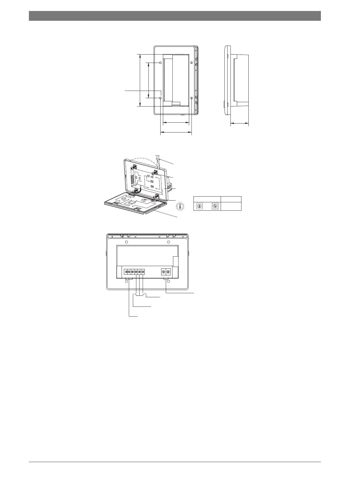
Installation dimensions:
As shown in the figure
on the right side.
Installation screw
holes (4 holes)
631
29
70.5
83.5
48.5
Fig.5-6
~
00 ~ 15
Rotate the flathead screwdriver slightly to
open the upper cover (at points).
Screws for fixing the centralised controller
(GB845/ST3.9*25)
Holder
Address
bits
Upper
cover
Bit location Address range
Fig.5-7
X Y
L
N
E
OFF
COM
ON
Communication interface with indoor interface
OFF—COM: Emergency stop switch, used to
shut down all air conditioners.
ON—COM: Emergency open switch, used to
start up all air conditioners.
Power connector of the
central controller 198-242V/AC
Fig.5-8
CLIMATE 5000 VRF 6720862458 (2017/05)
INSTALLATION METHOD | 5





 To Next Page