Preparing for installation
Compress Hybrid 3400i AW – 6721861825 (2023/08)
8
Suitable water treatment products (inhibitors/cleaning agent) are
available from the following manufacturers:
Table 5
4.2 Install the particulate filter
NOTICE
Pollution in the heating system may damage the indoor unit!
Dirt and pollution in the heating system may damage the indoor unit.
▶ Install a particulate filter in the heating return of the indoor unit.
The particulate filter must have the following characteristics:
• Mesh size: max. 0.6 mm
•Flow factor k
vs
: minimum 7 m³/h
•Magnetite separator
4.3 Heating system minimum volume and flow
A sufficient amount of energy stored in the system is required to avoid
multiple start/stop cycles, incomplete defrosting or unnecessary
alarms. Energy is stored in the heating system water volume, as well as in
the system components (radiators and underfloor heating).
For the defrost operation of the outdoor unit, a minimum volume and
flow must be ensured and permanently available.
The minimum volume can be provided by the open circuits (the
necessary zone valves/thermostats must be always fully open) and/or by
a buffer tank. For an optimal and most efficient defrost operation a
recommended volume is stated.
The minimum flow must be ensured within the minimum volume
available. If the minimum flow is not met, additional measures are
needed, e.g. differential bypass valve or parallel buffer. Note that if an
hydraulic separator is present it requires an additional heating circuit
pump.
In certain circumstances depending on the available energy stored in the
system, the auxiliary heater may be used to ensure the complete defrost.
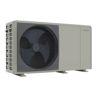
Table 6 Minimum volume and flow for outdoor unit CS3400iAW 4 OR-S
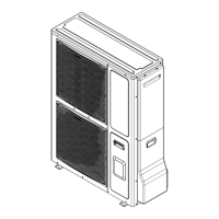
Table 7 Minimum volume and flow for outdoor unit CS3400iAW 6-8 OR-
S
4.4 Installing the piping
NOTICE
Danger of faults due to contaminants in pipework!
Solids, metal/plastic filings, flax and thread tape residue and similar
material can get stuck in pumps, valves and heat exchangers.
▶ Keep foreign bodies from entering the pipework.
▶ Do not leave pipe parts and connections directly on the ground.
▶ When deburring, make sure that no residue remains in the pipe.
CAUTION
Risk of injury due to refrigerant leakage!
Skin or eye contact with the refrigerant can cause frostbite. Risk of
suffocation due to inhalation of gases/vapours.
▶ Always wear suitable protective gloves and goggles when working
with refrigerant.
▶ Avoid skin or eye contact with the refrigerant.
▶ In case of skin or eye contact with the refrigerant, seek medical
attention.
▶ Do not inhale gases/vapours.
▶ Ensure sufficient ventilation at the workplace.
▶ Install refrigerant pipes between the outdoor unit and the indoor unit
according to the installation instructions of the outdoor unit.
▶ Mount connection sets (accessories) on the pipe as shown in figure
7.
▶ Push the connector onto the pipe up to the catch.
▶ Tighten union nut using a suitable tool.
Fig. 7 Assembly of the clamping ring screw fitting
[1] Pipe
[2] Pipe socket cap
[3] Locking ring
[4] O-ring (black for hydraulics)
[5] Connection part
▶ Install piping for the heating system in the building up to the
installation location of the indoor unit.
▶ Install insulated piping between the outdoor unit and indoor unit,
keeping the length of the piping as short as possible.
ADEY 01242 546700
www.adey.com
FERNOX 0330 100 7750
www.fernox.com
SENTINEL 01928 704330
www.sentinelprotects.com/uk
Outdoor Unit CS3400iAW 4 OR-S
Minimum Recommended
Underfloor/fan coils 13l 35l
Radiators 4l 13l
Minimum flow 15l/min
Outdoor Unit CS3400iAW 6-8 OR-S
Minimum Recommended
Underfloor/fan coils 27l 40l
Radiators 10l 15l
Minimum flow 15l/min

 Loading...


