Product description
5
Compress 3400i AWS – 6721825369 (2021/11)
3 Product description
3.1 Supplied parts
Fig. 1 Supplied parts
[1] CS3400iAWS 4 OR-S
[2] CS3400iAWS 6 OR-S, CS3400iAWS 8 OR-S, CS3400iAWS 10
OR-S
[3] Rubber pads (x4 pieces)
[4] Drain connector
[5] Rubber washer
[6] 5/8” to 1/2” Converter (only supplied with CS3400iAWS 4 OR-S)
3.2 Heat pump details
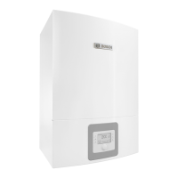
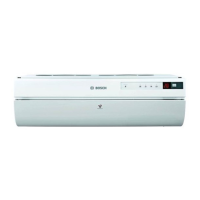
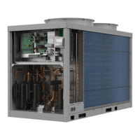
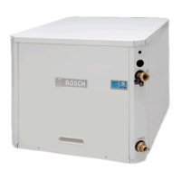
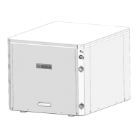
The CS3400iAWS outdoor unit is intended for connection to the AWS E,
AWS B or AWS M indoor units.
Possible combinations:
Table 3 Outdoor unit and indoor unit combinations
AWS E and AWS M are equipped with an integrated electric booster
heater.
AWS B are intended to work together with an external auxiliary heater
(electric, oil, gas heater), with mixer.
3.3 Declaration of conformity
This product conforms to European directives and supplementary
national requirements in design and operation. Conformity has been
demonstrated with the CE marking.
You can request the conformity declaration of the product.
Please refer to the address on the back of this manual.
3.4 Type plate
The data plate is located on the rear side of the outdoor unit. It contains
information on the output, part number, serial number, date of
manufacture, type and amount of refrigerant.
3.5 Heating system minimum volume and flow
A sufficient amount of energy stored in the system is required to avoid
multiple start/stop cycles, incomplete defrosting or unnecessary
alarms. Energy is stored in the heating system water volume, as well as in
the system components (radiators and underfloor heating).
For the defrost operation of the outdoor unit, a minimum volume and
flow must be ensured and permanently available.
The minimum volume can be provided by the open circuits (the
necessary zone valves/thermostats must be always fully open) and/or by
a buffer tank. For an optimal and most efficient defrost operation a
recommended volume is stated.
The minimum flow must be ensured within the minimum volume
available. If the minimum flow is not met, additional measures are
needed, e.g. differential bypass valve or parallel buffer. Note that if an
hydraulic separator is present it requires an additional heating circuit
pump.
In certain circumstances depending on the available energy stored in the
system, the auxiliary heater may be used to ensure the complete defrost.
Table 4 Minimum volume and flow for outdoor unit CS3400iAWS 4 OR-
S
Table 5 Minimum volume and flow for outdoor unit CS3400iAWS 6-10
OR-S
1
3
4
5
0010036359-001
2
6
AWS E / AWS B AWS M CS3400iAWS
444-S
4 4 6-S
448-S
4 4 10-S
Outdoor Unit CS3400iAWS 4 OR-S
Minimum Recommended
Underfloor/fan coils 13l 35l
Radiators 4l 13l
Minimum flow 15l/min
Outdoor Unit CS3400iAWS 6-10 OR-S
Minimum Recommended
Underfloor/fan coils 27l 40l
Radiators 10l 15l
Minimum flow 15l/min

 Loading...
