6 720 820 871 (2016/12)CR 400 | CW 400 | CW 800
Overview of control elements and symbols | 7
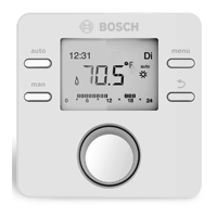
Fig. 2 Example for a standard display of a system with more than one heating circuit
[1] Value display
[2] Information line
[3] Outside temperature
[4] Text information
[5] Information graphic
[6] Time program
[7] Time marker (current time)
[8] Operating mode
[9] User interface status
6
1
3
8
2
9
4
5
7
Æ Fig. 2, page 7
Item Symbol Designation Explanation
1 Value display Display of current temperature:
• Room temperature for wall-mounted installation
• Heat source temperature for installation in heat source.
2 – Information line Display of time of day, day of the week and date.
3 Additional
temperature
display
Display of an additional temperature: outside temperature, temperature of the
solar collector or a DHW system (for further information Æ page 35).
4 – Text information E.g. the designation of the temperature currently displayed (Æ Fig. 2, [1]); a
designation for the room temperature is not displayed. If a fault is present,
corresponding information will be displayed here until the fault has been
rectified.
5 Information
graphic
Solar pump is in operation
DHW heating active.
DHW heating is switched off.
Burner is on (flame).
B Heat source is blocked (e.g. by an alternative heat source).
Table 4 Symbols on the standard display