6 720 820 871 (2016/12) CR 400 | CW 400 | CW 800
8 | Overview of control elements and symbols
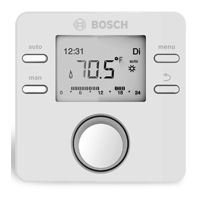
6 Time program Graphical display of the active time program for the heating circuit displayed. The
height of the bars represents roughly the desired room temperature in the
different time slots.
7 Time marker The time marker indicates the current time of day in the time program in
15 minute increments (= division of time scale).
8 Operating mode Heating is completely off (all heating circuits).
Chimney sweep mode is active.
Emergency operation is active.
E External heat requirement
auto System with one heating circuit in automatic mode (heating controlled by time
program)
HC2auto The displayed heating circuit operates in automatic mode. The standard display
refers only to the displayed heating circuit. Pressing the man key, the auto key
and changing the required room temperature in the standard display only affects
the heating circuit displayed.
Heating mode active in automatic mode in the displayed heating circuit
Setback mode active in automatic mode in the displayed heating circuit
Summer (off) System with one heating circuit in summer mode (heating off, DHW heating
active, Æ Chapter 5.3.4, page 25)
HC2Summer
(off)
The displayed heating circuit operates in summer mode (heating off, DHW
heating active). The standard display refers only to the displayed heating circuit
(Æ Chapter 5.3.4, page 25).
manual System with one heating circuit in manual operation
HC2manual The displayed heating circuit operates in manual operation. The standard display
refers only to the displayed heating circuit. Pressing the man key, the auto key
and changing the required room temperature in the standard display only affects
the heating circuit displayed.
Holiday until
10/6/2015
Holiday program active in system with one heating circuit
(Æ Chapter 5.5, page 31).
HC2Holiday until
10/6/2015
The holiday program is active in the displayed heating circuit and possibly for
DHW systems (Æ Chapter 5.5, page 31). The standard display refers only to the
displayed heating circuit.
9 User interface
status
A communication module is available in the system and a connection to the Bosch
server is active.
The key lock is active (hold down the auto key and the selector to activate or
deactivate the key lock).
Æ Fig. 2, page 7
Item Symbol Designation Explanation
Table 4 Symbols on the standard display
 Loading...

