Notification Appliance Circuit Module Wiring | en 11
Bosch Security Systems, Inc. Installation manual 2020.05 | 04 | 4998122260
5.1.3 Wiring interconnected loops with 12VDC or 24VDC power supplied by an
external power supply
This wiring scheme allows up to 12 D192G modules (NAC loops) triggered by a single
programmed alarm output.
Figure5.3: Wiring interconnected modules to a GSeries panel with power supplied by an external power supply
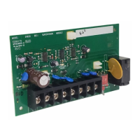
1 Last D192G module on the
interconnected NAC loop
8 Negative (-) connection from external
power supply and module COM to
panel’s COMMON (not to earth
ground)
2 Polarized notification devices 9 Positive (+) connection between
module’s ALRM terminal and the
power supply
3 560Ω, 2W EOL resistors (P/
N:F01U008725)
10 Conduit required for wiring between
external power supply and control
panel enclosure
4 First D192G module on the
interconnected NAC loop
11 Connection to either Relay A or Relay
B programmed output
5 GSeries control panel 12 Connection between module SUPV
ZONE and panel zone
6 UL Listed 12VDC or 24VDC regulated,
power‑limited auxiliary power supply
13 1kΩ EOL resistor (P/N:F01U011298)
7 Positive (+) connection from panel’s
AUX POWER to the AUX PWR IN
terminals of the modules (to power
modules)