10 en | Wiring Notification Appliance Circuit Module
2020.05 | 04 | 4998122260 Installation manual Bosch Security Systems, Inc.
5.1.2 Wiring separate loops with 12VDC power supplied by the panel
This wiring scheme allows two separate strings of modules (NAC loops) triggered by separate
programmed alarm outputs.
Figure5.2: Wiring separate module loops to a GSeries control panel supplying 12VDC power
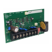
1 Last D192G module on the
interconnected NAC loop
7 Connection to Relay A programmed
output
2 Polarized notification devices 8 Connection to Relay B programmed
output
3 560Ω, 2W EOL resistors (P/
N:F01U008725)
9 Connection between module COM and
panel’s COMMON (not to earth
ground)
4 First D192G module on the
interconnected NAC loop
10 Connection between one module’s
SUPV ZONE terminal and panel zone
5 GSeries control panel 11 Connection between the other
module’s SUPV ZONE terminal and
panel zone
6 Positive (+) connection from panel’s
AUX POWER and the AUX PWR IN and
EXT PWR IN terminals of the modules
12 1kΩ EOL resistor (P/N:F01U011298)