Bosch Security Systems
Divar | Installation Manual | Hardware setup EN | 4-8
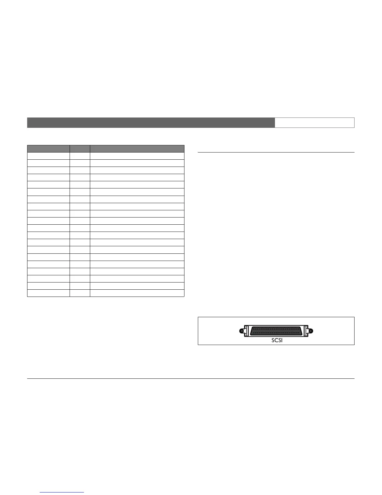
SCSI connection
The unit provides a 50-pin high density SCSI-2 port for connection of an
external storage system, for example, a LP (DVAD) or a RAID (DVAS) storage
array. To use this feature, connect the drive's SCSI cable to the SCSI-2
connector on the rear panel.
The Divar with internal DVD writer is delivered with a terminator connected to
the SCSI connector. Do not remove the supplied terminator from the SCSI
connector unless you connect a disk array!
The default SCSI ID of the Divar is 7. The SCSI ID of the internal DVD writer
is 6. If you are using a disk array make sure that the ID you select is different
from these IDs.
Adding additional storage arrays deletes all existing data!
Specification
Connector type: 50-pin narrow SCSI connector for external SCSI device
Bus format: Narrow (8 Bits) single-ended
Max. number of SCSI devices:6 (7 when Divar has no internal DVD writer)
Max. transfer rate: 20 Mbytes per second
Total max. cable length: Fast-20
2 to 4 SCSI devices 3m (uniformly spaced)
5 to 6 (7) SCSI devices 1.5m (uniformly spaced)
The internal SCSI cable length is approximately 17 cm.
This must be taken into account when calculating the
total cable length.
Alarm_in_6 6 Alarm input 6
Alarm_in_7 7 Alarm input 7
Alarm_in_8 8 Alarm input 8
Alarm_in_9 9 Alarm input 9
Alarm_in_10 10 Alarm input 10
Alarm_in_11 11 Alarm input 11
Alarm_in_12 12 Alarm input 12
Alarm_in_13 13 Alarm input 13
Alarm_in_14 14 Alarm input 14
Alarm_in_15 15 Alarm input 15
Alarm_in_16 16 Alarm input 16
Relay1_A 17 Relay 1 output pole 1
Relay1_B 18 Relay 1 output pole 2
Relay2_A 19 Relay 2 output pole 1
Relay2_B 20 Relay 2 output pole 2
Relay3_A 21 Relay 3 output pole 1
Relay3_B 22 Relay 3 output pole 2
Relay4_A 23 Relay 4 output pole 1
Relay4_B 24 Relay 4 output pole 2
System Ground 25 Chassis Ground
Signal name: Pin no. Description
25
1
26
50
Panel view