English–81 609 929 F67 • (04.10) PS
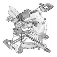
31 Locking screw for the slide rails
32 Scale for the bevel angle (vertical)
33 Angle indicator (vertical) for the left bevel angle
range
34 Setting knob for 33.9° bevel angle (vertical)
35 Multi purpose tool
36 Tightening knob for the length stop 37
37 Length stop
38 Sliding saw table extension
39 Clamping handle for the saw table extension
40 Scale for mitre angle (horizontal)
41 Knob for the setting of the bevel angle range (ver#
tical)
42 Spindle lock
43 Locking lever
**
44 Phillips screw (attachment of the swinging guard)
45 Phillips screw (attachment of the swinging guard)
46 Hex#head bolt for attaching the saw blade
47 Washer
48 Clamping flange
49 Tool spindle
50 Angle adapter for dust bag
51 Sawdust ejector
52 Clamping lever of the quick action clamp
53 Threaded rod of the quick action clamp
54 Holes for quick action clamp
55 Button for quick releasing the adjustment screw of
the depth stop
56 Depth stop
57 Screw for the length stop 37
58 Screws of the table insert
59 – 62
Adjustment bolts for the 0° basic setting (vertical
bevel angle)
63 Adjustment bolt for the 45° basic setting
(left vertical bevel angle)
64 Adjustment bolt for the clamping action of the
clamping handle 16
65 Adjustment bolts for the clamping action of the
clamp 5
66 Angle indicator (horizontal)
67 Adjustment screw of the fence extension
68 Hex#head bolts (14 mm) of the fence
0 601 B23 537 (Australia):
* 8 Button for unlocking the On/Off switch 27
** The locking lever 43 is not included.
Perform the operations described in the following
accordingly without the locking lever 43.
Not all the accessories illustrated or described are in
cluded in standard delivery.
4 MOUNTING
Avoid unintentional starting of the electro
tool. During mounting and for all work on
the electrotool itself, the main plug must
not be connected to the power source.
Items Included
Before putting the electro#tool into operation, check
that all of the items listed below have been delivered:
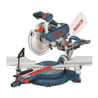
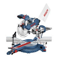
– Dual#bevel slide mitre saw with premounted saw
blade
–Dust bag 1
– Angle adapter 50 for dust bag
–Locking knob 14
– Open#end spanner 3
– Allen key 2
– Multi purpose tool 35 with hex#socket spanner
(14 mm) and screwdriver bit (hex#head 4 mm and
Phillips)
– Quick action clamp 23
Check the electrotool for possible damage.
Before further use of the electro#tool, check that all the
protective devices are fully functional. Any lightly dam#
aged parts must be carefully checked to ensure flaw#
less operation of the tool. All parts must be properly
mounted and all conditions fulfilled that ensure fault#
less operation.
Damaged protective devices and parts must be imme#
diately replaced by an authorised service centre.
Initial Operation
Remove all parts supplied carefully from the packag#
ing.
Remove all packing material from the electro#tool and
the accessories provided.
45°-0
 Loading...

