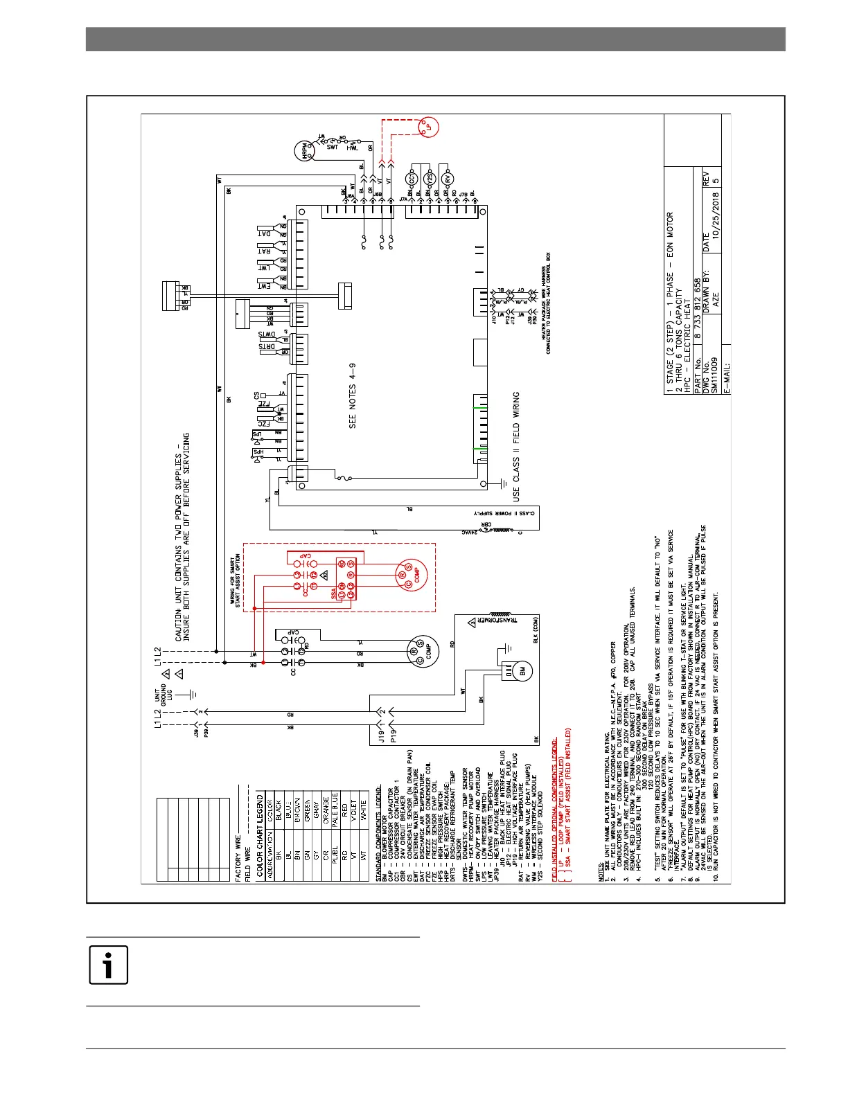
Wiring Diagrams | 31Heat Pump Controller
8733819577 (2019/02)Heat Pump Controller Subject to change without prior notice
Fig. 37 One Stage (2-Step) Single-Phase Unit with EON Motor and Electric Heat
ALARM STATUS LED - BLINK CODES
1
HIGH PRESSURE FAULT
2 LOW PRESSURE FAUL
3 CONDENDSER FREEZE CONDITION
4 CONDENSATE OVERFLOW FAULT
5 BROWNOUT FAULT
6 EVAPORATOR FREEZE CONDITION
THERMOSTAT
R C G O Y1 Y2 W1 W2 H RH
T1 - C
T1 - R
COMM
12 + - C
HPS
HPS
LPS
LPS
FZC
C
FZE
CON
X
X
EWT
EWT
LWT
LWT
RAT
RAT
DAT
DAT
SR C AUX C
10
9
8
7
6
5
4
3
2
1
8
7
6
5
4
3
2
1
4
3
2
1
5
4
3
2
1
X
X
L1
L2
HRP
HRP
LP1
LP2
X
ERT
ERT
DWT
DWT
24DC
RPM
PWM
GND
1
2
3
4
5
6
7
8
CS1
C
CS2
RV
C
HUM
RHV/SEL
C
1
2
3
4
5
6
7
8
1
2
3
4
HPC
F4
3 AMP
2
1
1
2
3
4
5
6
7
8
9
10
SERVICE PORT
P1 P2 P3 P4 P5
ALRDISPLAY
P6
P7
P8 P9 P10
5
4
3
2
1
F5 -1A
F6 -5A
F7- 5A
PUMP FUSES
TO ECM MOTOR
WIM
12V - + GND
1 2 4 5
FOR REFERENCE ONLY Actual unit wiring
may vary from this example. Always refer to the
wiring diagram attached to the unit.