Do you have a question about the Bosch IDP Premium BRBA-60HWD1N1-M18 and is the answer not in the manual?
Explains warning symbols and keywords used in the document.
Outlines critical safety precautions, hazards, and warnings for installation and operation.
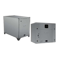
Provides detailed measurements for the heat pump unit's length, width, height, and depth.
Details the dimensions and openings for the back and bottom views of the unit.
Presents dimensional data for the right side and top views of the unit.
Lists essential checks and preparations required before installing the unit.
Provides instructions and precautions for safely moving and lifting the unit.
Specifies guidelines for selecting an appropriate installation location, considering clearances and environmental factors.
Details the process and requirements for mounting the unit on a rooftop curb.
Instructions for properly installing the condensate drain pipe, including trap requirements.
Guidelines for connecting the main power supply to the unit, including safety and circuit requirements.
Emphasizes the importance of proper electrical grounding for safety and unit protection.
Details on connecting low-voltage control wiring, thermostat, and other control devices.
Step-by-step instructions for powering on and initially operating the heat pump system.
Procedures for charging the system's refrigerant using the weigh-in method.
Method for adjusting refrigerant charge based on subcooling for outdoor temperatures above 55°F.
Explanation of how the unit's control system manages compressor and fan operation.
Identifies and describes the function of various sensors used in the system.
Details the unit's defrost cycle initiation and termination logic.
Explains the purpose and operation of the compressor crankcase heater.
Describes how the reversing valve functions in heating and cooling modes.
Outlines various safety and protection mechanisms within the unit's operation.
Lists error codes and their corresponding fault descriptions for troubleshooting.
Details parameters that can be checked on the control board for diagnostics.
Identifies and describes the various ports and components on the main control board.
Provides diagnostic flowcharts for specific error codes to identify and resolve issues.
Offers tables correlating sensor temperatures with their electrical resistance values.
Provides specific temperature-resistance data for T5 and Tf sensors.
Illustrates the electrical connections and wiring schematic for the unit.
Safety warnings and guidelines to follow when cleaning unit components.
Outlines routine inspection and cleaning tasks for optimal system performance.