EasyManua.ls Logo

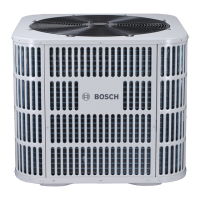
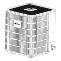
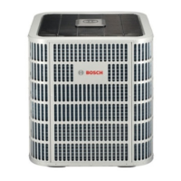
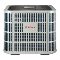
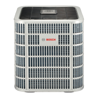
Bosch IDS BOVA60-15 User Manual

Bosch IDS BOVA60-15
44 pages
To Next Page IconTo Next Page
Page #1 background imageLoading...
Page #1 background image
Installation Instructions
Split System Heat Pump
Bosch IDS BOVA15
IDS Light Condensing Units | 2-5 Ton Capacity | R410A
BTC 761701317 A / 02.2022

Table of Contents

Question and Answer IconNeed help?

Do you have a question about the Bosch IDS BOVA60-15 and is the answer not in the manual?

Bosch IDS BOVA60-15 Specifications

General IconGeneral
Model NumberBOVA60-15
CategoryHeat Pump
RefrigerantR410A
Operating Temperature Range (Cooling)-10°C to 46°C
Operating Temperature Range (Heating)-20°C to 24°C

Summary

Key Symbols and Safety Instructions

Refrigerant Line Considerations

Refrigerant Line Brazing

Leak Check and Evacuation Procedures

Low Voltage Electrical Connections

High Voltage Electrical Requirements

System Start Up Procedures

System Charge Adjustment

System Operation and Troubleshooting

Error Code Troubleshooting

Troubleshooting C3 Error Code

Flowchart for diagnosing condenser coil sensor faults.

Troubleshooting E4 Error Code

Flowchart for diagnosing temperature sensor faults.

Troubleshooting E5 Error Code

Flowchart for diagnosing high/low voltage protection.

Troubleshooting E6 Error Code

Flowchart for diagnosing DC fan motor faults.

Troubleshooting E7 Error Code

Flowchart for diagnosing T5 sensor faults.

Troubleshooting E9 Error Code

Flowchart for diagnosing EEPROM faults.

Troubleshooting H0 Error Code

Flowchart for diagnosing communication faults.

Troubleshooting H8 Error Code

Flowchart for diagnosing pressure transducer faults.

Troubleshooting P0 Error Code

Flowchart for diagnosing control board overheating.

Troubleshooting P1/F1 Error Code

Flowchart for diagnosing high pressure protection.

Troubleshooting P2 Error Code

Flowchart for diagnosing low pressure protection.

Troubleshooting P3 Error Code

Flowchart for diagnosing compressor over current protection.

Troubleshooting P4 Error Code

Flowchart for diagnosing high compressor discharge temperature protection.

Troubleshooting P5 Error Code

Flowchart for diagnosing condenser coil temperature protection.

Troubleshooting P8 Error Code

Flowchart for diagnosing DC outdoor fan motor protection.

Troubleshooting PH Error Code

Flowchart for diagnosing low discharge superheat protection.

Troubleshooting LO-L9 Error Code

Flowchart for diagnosing IPM module protection.

Wiring Diagram Overview

Related product manuals