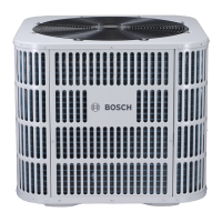
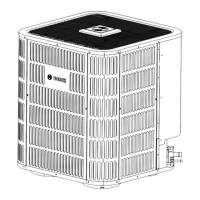
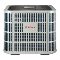
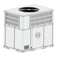
Do you have a question about the Bosch IDS BOVB20 and is the answer not in the manual?
Identifies warning symbols and keywords used in the document.
Outlines critical safety information, including electrical hazards and general warnings.
Instructions for downloading the Bosch EasyAir app and creating a user profile.
Provides the physical dimensions for different unit models.
Details maximum equivalent length and vertical separation for refrigerant lines.
Specifies clearances and environmental considerations for unit placement.
Steps to prepare the unit before installation, including checking for damage.
Guidelines for installing the unit on a support pad, including levelness and drainage.
Instructions for mounting the communication antenna for optimal signal strength.
Specifies the required sizes for refrigerant line and service valve connections.
Guidance on determining the necessary length of refrigerant lines.
Emphasizes the importance of insulating the suction line.
Precautions and guidelines for reusing existing refrigerant lines.
Best practices for routing refrigerant lines to prevent noise and ensure proper installation.
Step-by-step instructions for properly brazing refrigerant lines.
Procedure for pressurizing lines and checking for leaks using soapy solution.
Instructions for evacuating refrigerant lines and the indoor coil to a specific micron level.
Detailed steps for opening the suction and liquid service valves safely.
Table defining maximum wire lengths for low voltage connections based on gauge.
Diagrams illustrating low voltage unit connections.
Diagrams showing various thermostat wiring configurations for system control.
Specifies power supply requirements and safety warnings for live components.
Instructions for installing a separate disconnect switch at the outdoor unit.
Requirements for grounding the outdoor unit according to codes.
Step-by-step guide for initial system startup, including app integration.
Method for charging refrigerant by weight, including factory charge details.
Recommended method for charging above 55°F outdoor temperature.
Explanation of the variable speed system's control logic and settings.
Details on various sensors (T3, T4, T5, etc.) and the pressure transducer.
Function of the PEV for balancing system pressure before startup.
Explanation of the Demand Defrost Control (DDC) and defrost termination conditions.
Describes the function of the CCH to minimize refrigerant migration.
Explains reversing valve energizing during heat mode and de-energizing in cool mode.
Details various protection mechanisms like ODT, ambient, high/low pressure.
Lists fault codes and their corresponding descriptions for troubleshooting.
Guide to checking system parameters using the control board's "Check" button.
Identification and function of components on the main control board.
Flowcharts for troubleshooting specific error codes.
Visual representation of electrical connections for the unit.
Identifies gateway LEDs, buttons, and basic functionality.
Safety warnings and notices regarding unit cleaning procedures.
Required checks before each heating or cooling season.

