Do you have a question about the Bosch IDS BOVA15 and is the answer not in the manual?
Identifies warning symbols and keywords used in the document for safety.
Provides general safety warnings and important installation notes.
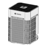
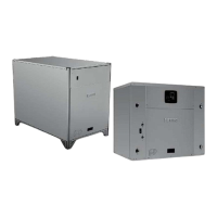
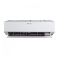
Provides physical dimensions for different Bosch IDS BOVA models.
Details maximum equivalent length and vertical separation for refrigerant lines.
Specifies clearance requirements for airflow, access, and noise.
Provides precautions for snow, ice, and freezing temperatures.
Advises on placement and maintenance in corrosive environments.
Instructions for checking and preparing the unit before installation.
Guidelines for installing the unit on a support pad or concrete slab.
Specifies connection sizes for refrigerant lines and service valves.
Details how to determine the necessary length of refrigerant lines.
Emphasizes the importance of insulating the suction line.
Provides precautions when reusing existing refrigerant lines.
Advises on preventing noise transmission and proper routing of refrigerant lines.
Step-by-step instructions for brazing refrigerant lines.
Procedures for pressurizing and checking refrigerant lines for leaks.
Steps for evacuating the system using a micron gauge.
Detailed instructions on how to safely open the service valves.
Table showing maximum wire lengths for low voltage connections.
Illustrates low voltage connection points to the control board.
Refers to diagrams for thermostat wiring configurations.
Specifies requirements for the high voltage power supply.
Instructions for installing a disconnect switch for high voltage.
Details grounding requirements for the outdoor unit.
Step-by-step guide to initiating system operation after installation.
Explains the weigh-in method for charging refrigerant.
Details the subcooling method for charging above 55°F outdoor temp.
Explains the variable speed system's control logic and settings.
Lists and describes the various sensors used in the system.
Describes the function of the PEV before compressor start-up.
Details the defrost control logic and conditions.
Explains the purpose and operation of the compressor crankcase heater.
Describes the reversing valve's function in heat and cool modes.
Details various protection mechanisms for the unit's components.
Lists fault codes, their descriptions, and associated sensors or components.
Provides a table to check system parameters and their values.
Identifies components and ports on the main control board for 24/36 ODU.
Identifies components and ports on the main control board for 48/60 ODU.
Provides troubleshooting flowcharts for specific error codes.
Provides tables relating temperature to sensor resistance and voltage.
Provides tables relating temperature to T5 sensor resistance and voltage.
Wiring diagram for 2/3 Ton outdoor units.
Wiring diagram for 4/5 Ton outdoor units.
Safety warnings and guidelines for cleaning the outdoor unit.
Steps for performing a pre-season inspection of the unit.