Do you have a question about the Bosch IDS 2.0 and is the answer not in the manual?
Explanation of warning symbols and keywords used in the document.
Important safety instructions and precautions for unit operation and installation.
Critical warnings regarding high voltage, grounding, and current leakage.
Precautions for handling refrigerant, hot surfaces, valves, and brazing.
Information on potential exposure to chemicals like Lead.
Explanation of the model number structure for Bosch IDS BVA2.0 indoor units.
Explanation of the model number structure for Bosch IDS BOVA2.0 outdoor units.
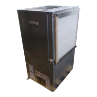
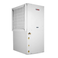
Physical dimensions, clearances, and specifications for indoor units.
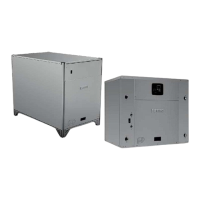
Physical dimensions, clearances, and specifications for outdoor units.
Performance data for units certified per AHRI Standard 210/240.
Detailed performance data for cooling and heating modes.
Identification of key components within 3-ton and 5-ton outdoor units.
Diagrams illustrating refrigerant path during cooling and heating operations.
List of abbreviations and descriptions for refrigerant system components.
Function of crankcase heater and oil return operation for compressor health.
Conditions, procedures, and settings for defrost operation.
Using force mode for diagnostics and details on indoor fan motor functions.
Checklists for initial unit preparation, installation, and start-up.
Configuration options and guidance for outdoor and indoor unit dip switches.
List of parameters and values for system diagnostics and verification.
Component identification for outdoor and indoor unit control boards.
List and explanation of fault codes and limited condition status codes.
Step-by-step troubleshooting guides for common fault codes.
Guides for common operational issues like blank display, no start, poor capacity.
Flowchart for diagnosing and resolving abnormal pressure issues.
Procedures for testing sensors, valves, motors, compressor, and switches.
Procedure for checking and adjusting refrigerant system charge.
Procedure for checking and replacing outdoor and indoor board fuses.
Wiring diagram and component layout for the outdoor unit control board.
Wiring diagram for the indoor unit control board.
| Refrigerant | R-410A |
|---|---|
| Stages | Variable |
| Voltage | 208/230 V |
| System Type | Air Source Heat Pump |
| Compressor Type | Inverter-driven |
| Sound Level | As low as 56 dB |
| Heating Capacity | Varies by model |
| Cooling Capacity | Varies by model |
| Noise Level | 45 dB to 60 dB |
| Operating Temperature Range (Heating) | -20°C to 35°C |
| Dimensions (Outdoor Unit) | Varies by model |
| Weight (Outdoor Unit) | Varies by model |
| Seasonal Coefficient of Performance (SCOP) | Not Available |