EasyManua.ls Logo

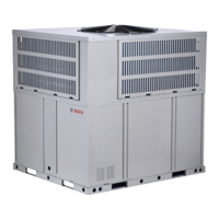
Bosch IDP Premium 18 SEER2 Series User Manual

Bosch IDP Premium 18 SEER2 Series
40 pages
To Next Page IconTo Next Page
Page #1 background imageLoading...
Page #1 background image
Installation Instructions
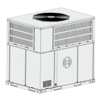
Inverter Ducted Packaged Heat Pump
Bosch IDP Premium
18 SEER2 Series | 3 Ton Capacity | R410A
BTC 761703103 A | 11.2022
Question and Answer IconNeed help?

Do you have a question about the Bosch IDP Premium 18 SEER2 Series and is the answer not in the manual?

Bosch IDP Premium 18 SEER2 Series Specifications

General IconGeneral
BrandBosch
ModelIDP Premium 18 SEER2 Series
CategoryHeat Pump
LanguageEnglish

Summary

Key to Symbols and Safety Instructions

Key to Symbols

Explains the visual symbols used to denote warnings and important information.

Safety

Provides critical safety warnings and precautions for installation and servicing personnel.

Component Location

Dimensions

Unit Dimensions

Details the length, width, and height measurements of the unit's exterior.

Dimensions - Back and Bottom

Dimensions - Left and Top

Installation

Pre-Installation

Outlines critical checks and preparations before commencing unit installation.

Rigging and Lifting

Provides instructions for safely rigging and lifting the heat pump unit.

Location Restrictions

Details environmental and clearance requirements for unit placement.

Rooftop Installation - Curb Mounting

Airflow Performance

Indoor Fan Motor Function

Four Stage Fan Control

Explains the four-stage fan control logic and dip switch settings.

Two Stage Fan Control

Explains the two-stage fan control logic and dip switch settings.

Anti-Cold Air Fan Delay

Details the anti-cold air fan delay feature for heating mode.

Passive Dehumidification (Optional)

Describes the optional passive dehumidification feature.

Ductwork

Condensate Drain Connection

Install Drain Pipe

Details the proper installation of the condensate drain pipe and trap.

Air Filter (Not Factory-Installed)

Electrical Wiring

Power Wiring

Covers the procedures and requirements for connecting the main power supply.

Grounding

Emphasizes the necessity and method for grounding the unit for safety.

Control Wiring

Guides on connecting control wires, including low voltage and high voltage separation.

Start Up

System Start Up

Details the step-by-step procedure for safely starting up the heat pump system.

System Charge Adjustment

Charging: Weigh-In Method

Describes the procedure for charging refrigerant using the weigh-in method.

Subcooling Charging and Refrigerant Adjustment In Cooling

Details the subcooling method for refrigerant charging in cooling mode.

System Operation and Troubleshooting

Control Logic Description

Describes the internal control logic and operation of the heat pump system.

Sensors (Thermistors/Pressure Transducer)

Details the various sensors and their functions within the system.

Defrost Description

Compressor Crankcase Heater Description

Reversing Valve Operation

Protection Functions

Fault Code Table

Parameter Point Check Table

Control Board Overview

Error Code Troubleshooting (ODU)

Error Code Troubleshooting (IDU)

Temperature and Resistance Relationship Tables (for Sensors)

Temperature and Resistance Relationship Tables (for T5)

Wiring Diagram

Maintenance

Cleaning Precautions

Outlines safety precautions and guidelines for cleaning the heat pump unit.

Regular Maintenance

Describes the regular inspection and maintenance schedule for the heat pump.
Related product manuals