22 en | MIC Non-IR Power Supply Units MIC Series Power Supplies
F.01U.141.598 | 1.0 | 2009.11 Installation Manual Bosch Security Systems, Inc.
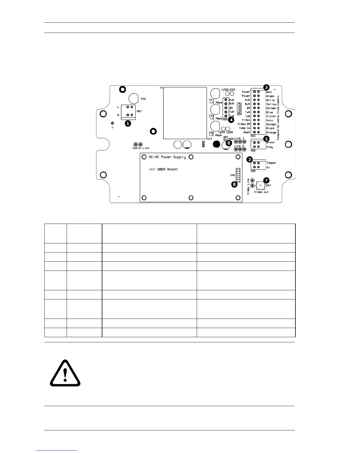
3.2 Non-IR Power Supply Layout and
Connections
The following figure shows the power supply PCB connections:
Figure 3.2 MIC-240PSU-UL layout
Item PSU
Head-end
Head-end Description Head-end Terminal
1 HD1 Power cable head-end Screw terminal
2 HD2 Tamper switch head-end Screw terminal
3 HD3 Composite cable head-end Screw terminal
4 HD4 and
HD5
Telemetry head-ends Screw terminal or Molex
crimp
5 HD6 Heater head-end Screw terminal
6 HD8 Optional 516 Kbd power
head-end
Molex crimp
7 CN1 Coax Video head-end BNC crimp
8 CN2/3 Auxiliary card head-end Plug in
CAUTION!
Do not Connect MIC PA or MIC IR units to a MIC-PSU with the
heater option enabled as this can result in damage to the
cameras. Ensure that the heater link is disabled if a MIC PA is
used and ensure an IR power supply is used with a MIC IR
camera unit.