MIC Series Power Supplies MIC IR Power Supply Units | en 35
Bosch Security Systems, Inc. Installation Manual F.01U.141.598 | 1.0 | 2009.11
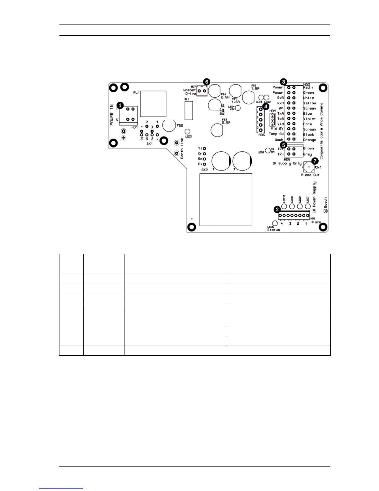
4.3 MIC IR Power Supply Layout and
Connections
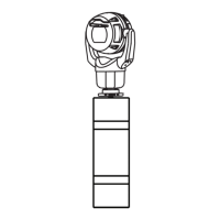
Figure 4.2 MIC-IR-240PSU layout
Item PSU
Head-end
Head-end Description Head-end Terminal
1 HD1 Power cable head-end Screw terminal
2 HD2 4-input alarm head-end Screw terminal
3 HD3 Composite cable head-end Screw terminal
4 HD4 and
HD5
Telemetry head-ends Screw terminal or Molex
crimp
5 HD6 IR lamps head-end Screw terminal
6 HD7 Washer drive head-end Molex crimp
7 CN1 Coax Video head-end BNC crimp