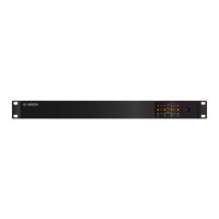
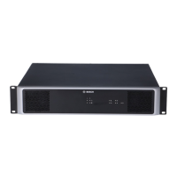
Rear panel
Number Element Description
1 AC power input and power
switch
2 Grounding screw Ground connection for DC only systems.
3 DC power input
4 CAN BUS port Connection with CAN bus, e.g. controller.
5 CAN ADDRESS selector switch HIGH-byte and LOW-byte for configuring the CAN
address of the device.
6 LINE 1-4 IN / THRU audio
input sockets (RJ-45)
Audio input (and through socket) for all
channels. Please refer to section Audio inputs,
page 16.
7 LINE IN L1 or L2 audio input
sockets (Euroblock)
Balanced audio input for channels 1 or 2. Please
refer to section Audio inputs, page 16.
8 Amplifier power output
sockets (70 V or 100 V)
Power output for speaker zones. Please refer to
section Audio output, page 18.
3.2
12 en | System overview PAVIRO Amplifier
18-Jun-2015 | 04 | F01U306898 Operation manual
 Loading...