Do you have a question about the Bosch Professional GCM 10 and is the answer not in the manual?
Essential safety precautions for all power tools, covering work area, electrical safety, and personal safety.
Specific safety advice for operating chop and mitre saws, including blade use and handling.
Understand the meaning of symbols for safe and correct operation, including PPE and danger areas.
Read all warnings and instructions to avoid injury from electric shock, fire, or other hazards.
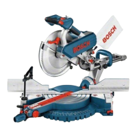
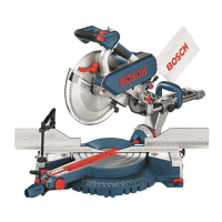
Stationary machine for straight and cross cuts, mitre, and bevel angles on various materials.
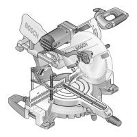
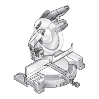
Numbered components correspond to graphic representations for easy identification.
Article number, power, voltage, frequency, speed, weight, and protection class.
Diameter, thickness, and mounting hole diameter for compatible saw blades.
Sound pressure and power levels, with uncertainty factor (K).
Vibration emission values (aH) and uncertainty factor (K) for user safety.
Ensure the power plug is disconnected during assembly to prevent accidental startup.
Check all supplied parts against the list before first use.
Install the tilt protector bar for machine stability and safety.
Attach the locking knob for securing mitre angles and ensure it's tightened.
Secure the machine to a level, stable surface using screws or clamps.
Mount the tool on a Bosch Saw Stand for stable support.
Dust from certain materials can be harmful or carcinogenic.
Use dust extraction, ensure ventilation, wear respirator, and follow regulations.
Use the provided dust bag for basic dust collection.
Connect a vacuum hose for external dust extraction.
Disconnect power, wear gloves, use correct blade speed and type.
Step-by-step guide to safely remove the saw blade.
Step-by-step guide to safely mount a new saw blade.
Disconnect power before any work on the machine itself.
Use the transport safety-lock for easier handling during transport.
Steps to unlock the tool arm from transport to working position.
Steps to lock the tool arm for safe transport.
Clamp workpiece firmly against fence using material clamp and threaded rod.
Disconnect power, check basic adjustments, and tighten locking knob before adjustments.
Set mitre angles from -47° to +47° using lever and indicator.
Set bevel angles from -2° to 47° using lever and indicator.
Ensure the power source voltage matches the machine's rating.
Steps to start the machine using the On/Off switch and lever.
Steps to safely turn off the machine.
Ensure blade clearance, protect blade, avoid warped workpieces, and support long pieces.
Stand aside of the blade, keep limbs clear, and avoid crossing arms.
Table of maximum workpiece dimensions for various angle settings.
Specifies the minimum workpiece size that can be clamped.
Indicates the maximum cutting depth at 0°/0° angles.
Guide on how to replace worn or defective insert plates.
Steps for performing a cut, including clamping, angle setting, and operation.
Guidance for sawing curved or round workpieces safely.
Two methods for sawing profile strips: against fence or flat on table.
Recommend making trial cuts on scrap wood for mitre angle settings.
Table providing instructions for sawing floor strips/mouldings.
Disconnect power before any adjustment work.
Procedure to align the horizontal angle indicator with the scale.
Procedure to align the vertical angle indicator with the scale.
Steps to align the fence parallel to the saw blade.
Procedure to set the vertical bevel angle to 0°.
Steps to set the vertical bevel angle to 45°.
Steps to prepare the tool for transport, including removing accessories.
Guidance on how to carry the machine safely.
Disconnect power before maintenance; contact service for failures.
Instructions for cleaning the tool, ventilation slots, and blade guard.
List of available accessories like extension bars and saw blades.
Information on how to contact customer service for repairs, spare parts, and advice.
Contact details for service centers in various regions.
Instructions for environmentally friendly recycling of the machine and packaging.





 Loading...