10 en | System Overview Battery Charger
180110011Aa | V1.1 | 2011.05 Installation and Operation manual Bosch Security Systems B.V.
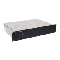
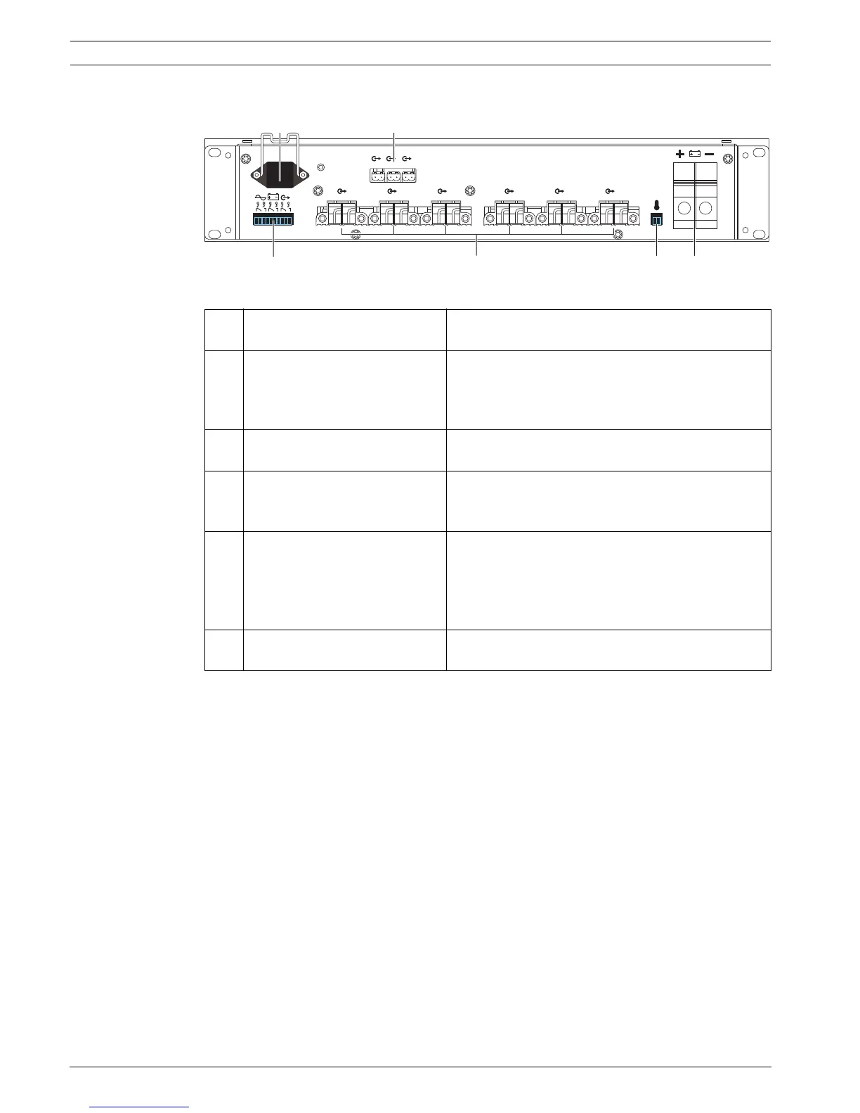
3.4.2 Connections on the rear panel
Figure 3.2 Rear view of battery charger
A Mains power socket Socket for connecting the battery charger to the
mains power. The socket has a built-in strain relief.
B Auxiliary output terminals Three terminals for connecting auxiliary outputs (5
A max.) to power modules of the Voice Alarm
System that do not have mains power inputs. The
outputs are protected by a fuse (Faux1 to Faux3).
C Temperature sensor socket Socket to connect the temperature sensor (see
section 6.6 ).
D Main output terminals Six output terminals to connect to the back-up
power terminals of VAS equipment (40 A max.).
The outputs are protected by a fuse (F1 to F6).
E Output contacts Fail-safe, dry contact, three-pole SPDT switch (C-
NC-NO), allowing 1A at 24 Vdc or 0,5 A at 120 Vac:
- Mains status (5 sec. of delay after mains fault)
- Battery status
- Output voltage status
F Battery terminal Terminal for connecting the battery leads (150 A
max.).
1
7 8 9
23 456
A B
E
D C F