-6-
<<.6+5B
!""(
To use the Product, the imager cable must be
attached to the handheld display unit. To
connect the cable, make sure the key and slot
are properly aligned. Once they are aligned,
finger-tighten the knurled knob to hold the
connector in place.
#"#""!(
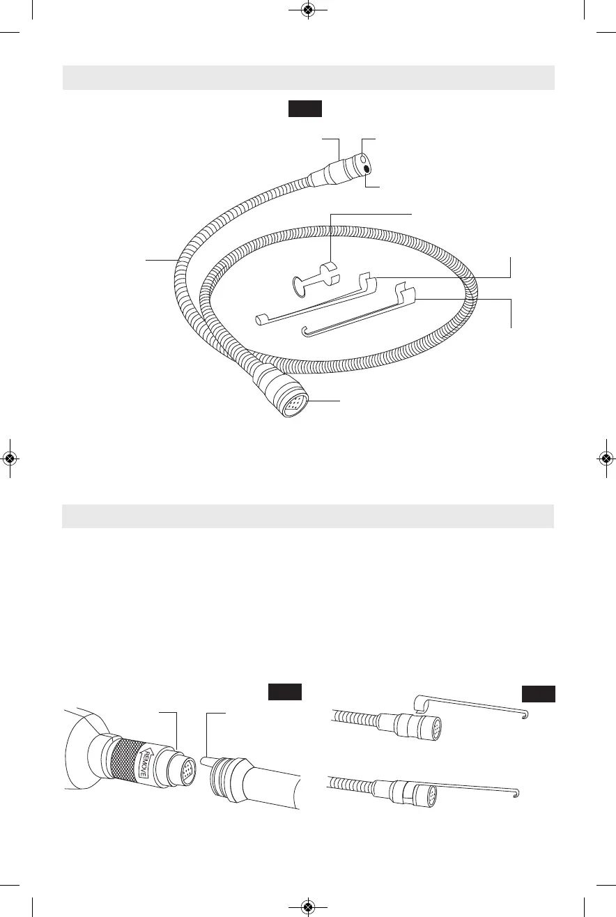
The three included accessories, (mirror, hook
and magnet) attach to the imager head in the
same way. To connect, hold the imager head,
slip the semicircle end of the accessory over
the flats of the imager head, then rotate the
accessory a 1/4 turn so the long arm of the
accessory is extending out.Always direct the
cord toward the rear, and away from the shear.
Keep it away from sharp edges.
>7,=287*5.<,;29=287*7-"9.,2/2,*=287<
IMAGER CABLE CONNECTOR
IMAGER CABLE
IMAGER HEAD
MIRROR
MAGNET
HOOK
KEY
SLOT
FIG. 2
FIG. 3
FIG. 4
9=2,*5*+5..70=1E66-2*6.=.;27,5>-.-@2=1 "
3’ (9.5mm diameter) included with PS91
LED
CAMERA