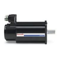
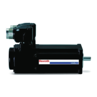
① Lid
② Seal
③ Terminal block U-V-W
④ PE connection
⑤ O-ring
⑥ Adapter plate mounting screws
⑦ Safety cover of the connection thread of the cable gland
⑧ Adapter plate for cable gland
⑨ Terminal strip (brake, temperature sensor)
⑩ Purging gas connection (only applicable to Ex-type mo‐
tors)
⑪ Clamping screws for setting the outgoing cable direction
(4 pcs.)
Fig. 9-1: Rotating terminal box (option D, E, G, H)
2. Check the outgoing cable direction and rotate the terminal box if neces‐
sary.
● Detach the terminal box.
Unscrew the mounting screws ⑪ and rotate the terminal box by 90
to max. 180 degrees to the desired outgoing direction.
● Attach the terminal box.
Screw in the mounting screws ⑪ and tighten them.
Tightening torque of the screws ⑪: 6.5 Nm (±10%)
WARNING! Improperly inserted or missing seals may lead to loss of the
motor protection and to explosion hazard of Ex-type motors.
⇒ There is a seal between the terminal box and the motor housing. After
having rotated or retightened the terminal box, check it to verify that the
seal is in a proper state and in its correct position.
3. Turn out the safety cover of the cable gland ⑦.
4. Detach the adapter plate ⑧ from the terminal box.
5. Firmly secure the adapter plate to the metric cable gland on the power
cable.
DOK-MOTOR*-IDYN*A*EXPD-IB05-EN-P Bosch Rexroth AG 37/69
Rexroth MAD and MAF Motors in EX px d Design acc. to ATEX Directive 2014/34/EU
Connection system

 Loading...


