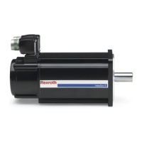
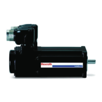
9.4 Encoder connection
A 15 meter-long connection cable is connected with the explosion-protected
motors. This connection cable has been connected with the encoder at the
factory. After motor assembly, connect this connection cable with another
● encoder cable of Rexroth, e.g. RKG4200 (for connection on encoder in‐
terface ENS on IndraDrive controllers) or
● encoder cable RKG4202 (for connection on a terminal strip)
with the IndraDrive controller.
Explosion hazard due to improper handling
during the connection of the motor!
The junction to/on the motor drive device must be located outside of the ex‐
plosive atmosphere.
● The encoder housing on the motor may no longer be opened
in principle! Do not remove any of the screws on the encoder
housing.
● Please observe the detailsl of the project planning manual of
the drive device and the details about pin assignment in the
motor project planning manual DOK-MOTOR*-MAD/
MAF****-PRxx-xx-P in chapter 8 "Encoder Connection".
9.5 Equipotential bonding conductor
Explosion hazard due to improper handling
during the connection of the motor!
According to EN 60079-0:2009, chapter 15.4, the equipotential bonding at
the motor has to be connected with a separate cable with min. 4 mm² cross-
section (MAF225C-0150 with min. 25 mm²) in addition to the grounding wire.
To connect the equipotential bonding conductor, the motors have the follow‐
ing connection possibilities on the motor flange:
Frame size Clamping mode Remark
100 ... 180 Terminal connector For cable cross-sections up to 10mm²
225 Brass screw M12 To connect a cable via ring terminal for thread M12
Tab. 9-2: Clamping mode for equipotential bonding conductor
DOK-MOTOR*-IDYN*A*EXPD-IB05-EN-P Bosch Rexroth AG 41/69
Rexroth MAD and MAF Motors in EX px d Design acc. to ATEX Directive 2014/34/EU
Connection system

 Loading...


