9.3 Power connection double cabling
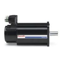
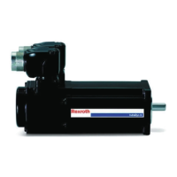
① Motor
② Terminal boxes
③ Holding brake (option)
④ Equipotential bonding motor
⑤ Equipotential bonding machine
⑥ Connection designations on the Rexroth drive controller
⑦ Purge gas ducts to the control device of motor purging
Fig. 9-4: Connection scheme for double cabling in Ex-areas
● The brake connections are assigned only if the motor was
manufactured with the "brake" option.
● Only one contact pair of PTC thermistor connections 3-4 and
5-6 is connected to the motor cable.
● Do not remove or damage the seal glued into the cover.
● Observe the size of the threaded cable connection and con‐
nection thread for the cable inlet into the terminal box.
● The connections of the motor windings in the terminal box
may not be removed.
● The through hole into the motor housing should not be
closed or sealed.
Bosch Rexroth AG DOK-MOTOR*-IDYN*A*EXPD-IB05-EN-P40/69
Rexroth MAD and MAF Motors in EX px d Design acc. to ATEX Directive 2014/34/EU
Connection system

 Loading...


