Quick coupling thread size
Allowed tightening range [Nm] between
the components of the quick coupling
1/8" ... 1/4" 23 ... 25
1/2" 28 ... 30
Tab. 9-8: Allowed tightening torque of the quick coupling
● that the allowed screw-in depths and tightening torques at the motor are
kept.
Frame size MAF ... Connection thread
Max. allowed screw-
in depth [mm]
Allowed tightening
torque [Nm]
100 G1/8" 14 14 ... 15
130 G1/4" 14 18 ... 20
160 ... 225 G1/2" 18 27 ... 30
Tab. 9-9: Coolant connection thread, allowed tightening torques and screw-in
depths
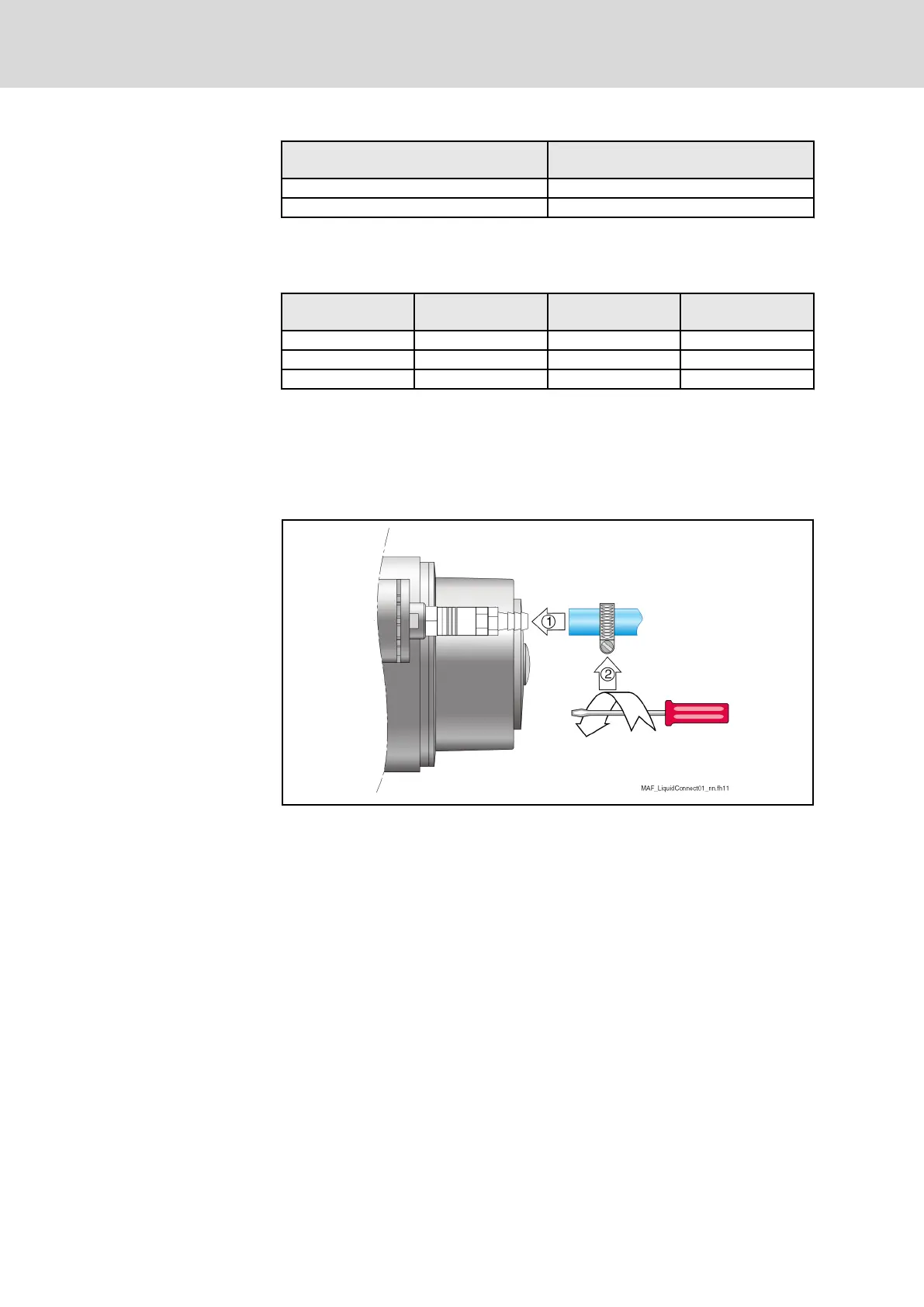
Once the quick coupler has been attached to the motor, the coolant hose can
be slipped over the threaded nozzle and fastened.
When selecting the coolant hose, ensure you use the required inside hose di‐
ameter d
i
according to Tab. 9-6.
Fig. 9-11: Connecting the coolant hose(example)
When mounting the coolant hose, proceed as follows:
1. Remove the protective caps from the coolant port threads on the motor
and screw in the pre-assembled quick coupling.
2. Push the tube onto the connection piece (threaded adapter). Do not
bend or damage the motor-sided screw connection.
3. Screw the tube end with the mounting clamp tightly above the connec‐
tion piece.
● In service cases, the quick coupling can be disconnected from the
lock nipple by means of the coupling. It is not necessary to discon‐
nect the tube connection.
If a different connection method is used on the tube side, other mounting
steps may be required. Mounting instructions can be obtained from the man‐
ufacturer.
Bosch Rexroth AG DOK-MOTOR*-IDYN*A*EXPD-IB05-EN-P48/69
Rexroth MAD and MAF Motors in EX px d Design acc. to ATEX Directive 2014/34/EU
Connection system