Do you have a question about the Bosch REXROTH VT-HDT Series and is the answer not in the manual?
Highlights the test device's role in simplifying hydraulic system commissioning and troubleshooting.
Critical warnings for users, emphasizing familiarity with the system and operating at own risk.
Lists part numbers and types for the test device, cables, and power supply unit.
Emphasizes qualified personnel, intended use, correct connections, and careful handling.
Details the test device's intended use for proportional valves with OnBoard Electronic (OBE).
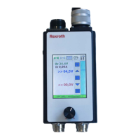
Describes the brightly lit TFT touchscreen, its intuitive use, and resistive nature.
Explains voltage application to terminals A, B, D, E and setpoint/actual value connections F, C.
Covers the '24V-> C, F: B (E)' range setting and its implications for terminal connections.
Warns about potential defects or machinery movement from the '24V-> C, F: B (E)' setting.
Signals are looped through and measured; setpoint specification is not possible.
Internal setpoint generation and output; setpoint adjusted via potentiometer or touchscreen.
Required for system work; setpoint active only when button is pressed.
Safety notes for 'Simulator mode' and the 'Dead man's handle' not being a safety device.
Setpoint adjustment using a potentiometer; touch functions are inactive.
Sockets for recording setpoint and actual values with external devices like data loggers.
Cautionary note to connect only devices with potential-free measuring inputs.
Option to display setpoint, actual value, Uv, and Iv in the ANALOG screen.
Detects valve plugging/unplugging and identifies V- or mA range for selection.
Setpoint output via a ramp function with adjustable steepness and rate.
Enables automatic setpoint output with adjustable profiles and timed intervals.
Switchable resistance for accurate 'Actual value' readout in external mode without external burden.
Shows available ranges, selection logic, and standard/special connection configurations.
Displays power supply, setpoint, and actual values digitally, with control options.
Presents analog curves for setpoint, actual value, Uv, and Iv.
Allows configuration of Dead Man's Handle, Potentiometer, Valve Detection, Ramp, and Interval.
Illustrates the physical layout of the test device, including input/output ports and controls.
Details the input/output connectors and switching valve connections with material specifications.
Provides dimensions, weight, protection rating, temperature, and humidity parameters.
Outlines supply voltage, current, protection, fuses, output voltage, and burden resistance.
Specifies connector types and part numbers for valve input/output and measuring sockets.
Details the service case design, dimensions, and included components like the test device and power supply.
Technical data for the power supply unit, including operating voltage, current consumption, and dimensions.
Information on the OBE connection cable, its connectors, and length for linking the test device to valves.
Details the switching valve cable, its connectors, and length for connecting to switching valves.
States that the products contain no hazardous substances and have no negative environmental impact.
Provides instructions for returning products for disposal and handling of packaging materials.
| Supply voltage | 24 VDC |
|---|---|
| Max Operating Pressure | 350 bar |
| Housing Material | Aluminum |
| Seal Material | NBR |
| Protection Class | IP65 |
| Series | VT-HDT |
| Voltage | 24 V |