Transport and storage 23/40
RE 30110-B/11.2012, VT-VSPA2-1-2X/V0/T., Bosch Rexroth AG
In addition, a measuring socket (v) is intended for setting the command values. The
measuring points are selected via the measuring point selector switch on the front
plate. The signal of the measuring socket (v) is also connected to the male multi-
point connector.
Table 7: Measuring points and measurement signals
Measuring point Switch position Measurement signal "v"
Internal command value 0 ±100 % = ±10 V
Command value call-up 1 1 ±100 % = ±10 V
Command value call-up 2 2 ±100 % = ±10 V
Command value call-up 3 3 ±100 % = ±10 V
Command value call-up 4 4 ±100 % = ±10 V
Zero point offset "Zw" 5 ±30 % = ±3 V
1 composite signal of the command values 6 ±100 % = ±10 V
Ramp output signal 7 ±100 % = ±10 V
Not connected 8
Clock frequency 9 Rectangular signal ±15 V
Ramp time "t1" A 10 mV to 10 V
Ramp time "t2" B 10 mV to 10 V
Ramp time "t3" C 10 mV to 10 V
Ramp time "t4" D 10 mV to 10 V
Ramp time "t5" E 10 mV to 10 V
Current ramp time "t" F 10 mV to 10 V
6 Transport and storage
There are no special transport instructions for this product. You must, however,
observe the notes in chapter 2 "General safety instructions" and comply with the
environmental conditions for storage and transport which are detailed in the techni-
cal data of the data sheet.
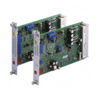
6.1 Storing the VT-VSPA2-1-2X
Proceed as follows in order to prepare the amplifier card for storage and further use:
▶ Use the original packaging or an ESD-compliant packaging for storage.
▶ Comply with the maximum admissible transport temperature of –25°C to +85°C
and the admissible storage temperature of 5°C to 40°C and ensure a relative air
humidity of 0% to 65%.
▶ Protect the amplifier card from dust, humidity and direct sunlight (100% UVprotection).
▶ Additional ozone formation or condensation close to the storage area must
beprevented.
 Loading...


