Do you have a question about the Bosch Rexroth WGM and is the answer not in the manual?
Defines the applications and limitations for oil humidity sensors.
Explains how the sensor measures humidity and temperature.
Describes the humidity sensor element and output options.
Describes the temperature sensor and output options.
Explains IO-Link capabilities for data access and parameter setting.
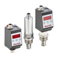
Lists the three basic types of WGM sensors (WGM-B, WGM-D, WGM-R).
Explains how to interpret the product's model code.
Lists the items included with the sensor.
Explains how information is presented in the manual for clarity.
Details how safety instructions are structured and presented.
Provides a glossary of warning signs and their meanings.
Key precautions for using the device safely and correctly.
General risks associated with device installation and maintenance.
Instructions for handling and storing the device to prevent damage.
Critical safety precautions regarding electrical, chemical, and pressure hazards.
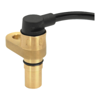
Guidance on physically mounting the sensor and ensuring proper immersion.
Specific advice for proper sensor placement and immersion.
Instructions for connecting the device's electrical interfaces.
Steps for powering up the device and initial checks.
Interpretation of LED indicators for switching output status.
Explanation of how to navigate menus using the device's buttons.
How to activate/deactivate and use the key lock function.
Describes the hierarchical menu structure of the device.
How to adjust fundamental device parameters like units and assignments.
Procedure for resetting the device to its default configuration.
Option to disable automatic error assessment and troubleshooting.
How to select units for humidity (%) and temperature (°C/°F).
Configuring the behavior and assignment of switching outputs.
Adjusting how often the display refreshes or switching it off.
Managing the device's keypad lock for security.
Detailed settings for individual switching outputs.
Setting the output behavior (hysteresis, window, frequency).
Defining the thresholds for switching output activation and deactivation.
Setting delays for switching output activation and deactivation.
Procedure for verifying the functionality of switching outputs.
Customizing how LEDs indicate output status (normal/inverted).
Settings for the analog output signals (current/voltage).
Setting humidity/temperature for max and min analog signal output.
Selecting the output signal type (e.g., 4-20 mA, 0-10 V).
Procedure for verifying analog output signals.
Accessing event logs, error messages, and diagnostic data.
Viewing recent events and entries in the log book.
Accessing and clearing error messages.
Displaying and deleting stored maximum/minimum values.
Configuring logging and setting delays for min/max value storage.
How the WGM-B powers on and how parameters are set via IO-Link.
Restoring factory settings and details on switching/analog outputs for WGM-B.
Checking sealing fittings for leak-tightness.
Recommended methods and agents for cleaning the sensor.
Guide to diagnosing and fixing errors.
Information for contacting Bosch Rexroth for support.
Instructions for sending the device for manufacturer repair.
Precautions before disassembling the device.
List of error codes, their causes, and remedies.
Common faults in switching/analog outputs and their causes/remedies.
How to dispose of the device and electronic components safely.
Overview of physical and operational specifications.
Detailed specifications for the WGM-B sensor.
Ambient temp, voltage, materials, protection class for WGM-B.
Accuracy, analog output, and switching output details for humidity.
Accuracy, analog output, and load details for temperature.
Detailed specifications for WGM-R and WGM-D models.
Display, operation, memory, consumption, and humidity accuracy for WGM-R/WGM-D.
Fastening, weight, housing, and protection class for WGM-R and WGM-D.
Details on output types for WGM-B versions.
Details on switching, IO-Link, and analog outputs for WGM-B versions.
Details on output types for WGM-R/WGM-D versions.
Details on switching, IO-Link, and analog outputs for WGM-R/WGM-D versions.
Pin descriptions for WGM-B connectors.
Pin descriptions for standard and IO-Link connectors on WGM-B.
Pin descriptions for WGM-R/WGM-D connectors.
Pin descriptions for connector A and sensor socket on WGM-R/WGM-D.
Specifies the display ranges for humidity and temperature measurements.
Specifies the display ranges for humidity and temperature measurements.
Lists current default settings for switching and analog outputs.
Lists current default settings for switching and analog outputs.
Visual representation of the device's menu structure and navigation paths.
Visual representation of the device's menu structure and navigation paths.
| Category | Measuring Instruments |
|---|---|
| Manufacturer | Bosch Rexroth |
| Data Transmission | Ethernet |
| Output signal | Ethernet |
| Protection class | IP67 |