| 35
Installation Instructions
Singular Combi Boiler - BTC 439003301 B (2021/07)
6.5 Vent Termination
WARNING:
Air intake must be protected from any debris.
When connecting to the air intake connector and exhaust
flue connector, all connecting parts must be installed
properly.
Maintain 12" (300 mm) min. (18" (450 mm) min. for
Canada) clearance above highest-anticipated snow level.
Maximum of 24" (600 mm) above roof.
Install a bird screen at the end of the intake air pipe and
exhaust pipe.
Before installing the boiler, determine what type of vent termination is appropriate
for the installation location and situation. The subsections that follow describe
some typical venting confi gurations, but do not include all possible options.
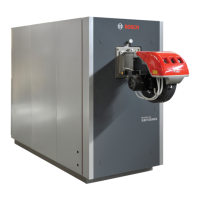
6.5.1 Single-Pipe Sidewall Venting
Figure 36
3
Schedule 40 PVC Pipe
10" (254 mm) min.
12" (300 mm) min.
CAUTION:
Single-pipe venting requires that adequate combustion air
be provided in end-use installations per NFPA 54 C.9.3.2.
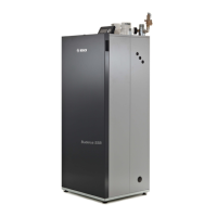
6.5.2 Two-Pipe Sidewall Venting
Internal view
Figure 37
Intake air
Exhaust gas
10" min.
External view
Figure 38
12" (300 mm) min.
Intake air
Less than 45°
Exhaust Gas
12" (300 mm) min.
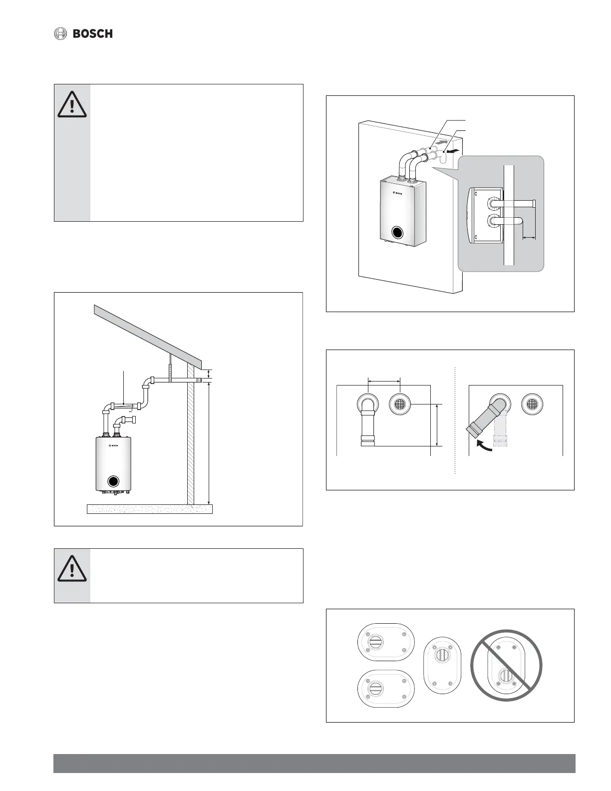
If the side wall vent termination kit is used, refer to the fi gure below for the
orientation of the vent.
The following terminations can also be used:
IPEX Low Profi le Termination Kits:
2 in Low Profile Vent Kit #196984
3 in Low Profile Vent Kit #196985
Figure 39
 Loading...