EasyManua.ls Logo

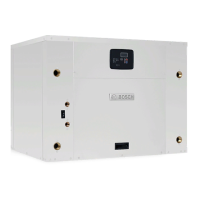
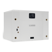
Bosch TA061 User Manual

Bosch TA061
28 pages
To Next Page IconTo Next Page
Page #1 background imageLoading...
Page #1 background image
Installation and Maintenance Manual
TA Series
6 720 220 046
Revised 03-11

Questions and Answers:

Bosch TA061 Specifications

General IconGeneral
BrandBosch
ModelTA061
CategoryHeat Pump
LanguageEnglish

Summary

Initial Inspection

General Description

Provides the best combination of performance and efficiency. Safety devices are built in for maximum system protection.

Moving and Storage

Instructions for handling and storing units to prevent damage and ensure safe stacking procedures.

Safety Considerations

Important safety precautions for installation and servicing, including electrical shock hazards and personal protective equipment.

Location

Guidance on selecting a suitable indoor location that allows for maintenance, fluid, electrical, and duct connections.

Installation

Steps for removing shipping blocks and loosening compressor mounting bolts before installation.

Mounting Vertical Units

Instructions for mounting vertical units, including options for air return and placement on vibration absorbing pads.

Mounting Horizontal Units

Condensate Drain

Details on connecting the drain line, ensuring proper pitch, and installing traps to prevent condensate backup.

Duct System

Piping

Guidelines for supply and return piping, material selection, and insulation to prevent condensation and heat loss/gain.

Electrical

Requirements for field wiring, compliance with codes, and phase balancing for three-phase units.

ECM Interface Board

Thermostat Connections

Details on connecting the thermostat to the ECM interface board and the functions of various terminals.

Motor Profile Air Flow Table

Considerations

Important considerations for thermostat wiring, voltage supply, and wire gauge selection for optimal performance.

Safety Devices and the UPM Controller

Safety Controls

High pressure, low pressure, freeze protection, and condensate overflow sensors that protect the unit.

UPM Controller Features

Includes anti-short cycle, random start, low pressure bypass, power protection, and malfunction output features.

Electric Heater Package Option

Considerations

Guidelines for wiring, voltage supply, wire gauge, and additional controlled devices for electric heater packages.

Well Water Systems

Sequence of Operation Two-Stage Units

Explains cooling and heating modes, compressor stages, fan control, and auxiliary/emergency heat operation.

Installation of Pressure Regulating Valves

Cooling Tower/Boiler Systems

Earth Coupled Systems

System Checkout

Unit Start-Up

Step-by-step guide for starting up the unit after installation, covering thermostat settings and operational verification.

Heat Recovery Package

Description of the heat recovery option, its function, and considerations for freezing conditions.

Water Tank Refill

Initial Start-Up

Procedure for refilling the water tank and performing initial start-up for the heat recovery system.

Maintenance

Troubleshooting

Guide to identifying and resolving common problems, including no flow, low flow, and temperature issues.

Well Water Application

System Components and Connections

Diagram illustrating the components and connections for a well water application.

Cooling Tower/Boiler Application

System Components and Connections

Diagram illustrating the components and connections for a cooling tower or boiler application.

Earth Coupled Application

System Components and Connections

Diagram illustrating the components and connections for an earth coupled application.

Typical Wiring Diagram

Single Phase ECM Blower Motor

Wiring diagram for units with a single phase ECM blower motor.

Typical Wiring Diagram

Single Phase ECM Blower Motor-Electric Heat

Wiring diagram for units with a single phase ECM blower motor and electric heat.

Operating Pressures & Temperatures

UNIT CHECK-OUT SHEET

Related product manuals