6 720 220 046
Revised 03-11 Subject to change without prior notice
3
TA Series
TABLE OF CONTENTS
Model Nomenclature .................................................................................... 3
Initial Inspection .......................................................................................... 4
General Description ..................................................................................... 4
Moving and Storage ..................................................................................... 4
Safety Considerations .................................................................................. 4
Location ....................................................................................................... 4
Installation ................................................................................................... 4
Condensate Drain ........................................................................................ 5
Duct System ................................................................................................. 6
Piping .......................................................................................................... 6
Electrical ...................................................................................................... 6
Thermostat Connections ............................................................................. 7
Safety Devices & the UPM Controller ........................................................... 9
Electric Heater Package Option ................................................................. 10
Sequence of Operation Two-Stage Units .................................................... 11
Well Water Systems .................................................................................... 11
Installation of Pressure Regulating Valves .................................................. 12
Cooling Tower / Boiler Application ............................................................. 12
Earth Coupled Systems .............................................................................. 12
System Checkout ....................................................................................... 13
Unit Start-Up .............................................................................................. 13
Heat Recovery Package ............................................................................. 13
Maintenance .............................................................................................. 15
Well Water Application ............................................................................... 16
Cooling Tower/Boiler Application .............................................................. 17
Earth Coupled Application ......................................................................... 18
Wiring Diagrams ......................................................................................... 19
Single Phase ECM Blower ...................................................................... 19
Single Phase ECM Blower—Electric Heat ................................................ 20
Operating Pressures & Temperatures ........................................................ 21
Unit Check-Out........................................................................................... 25
Trouble Shooting ........................................................................................ 26
Table of Contents
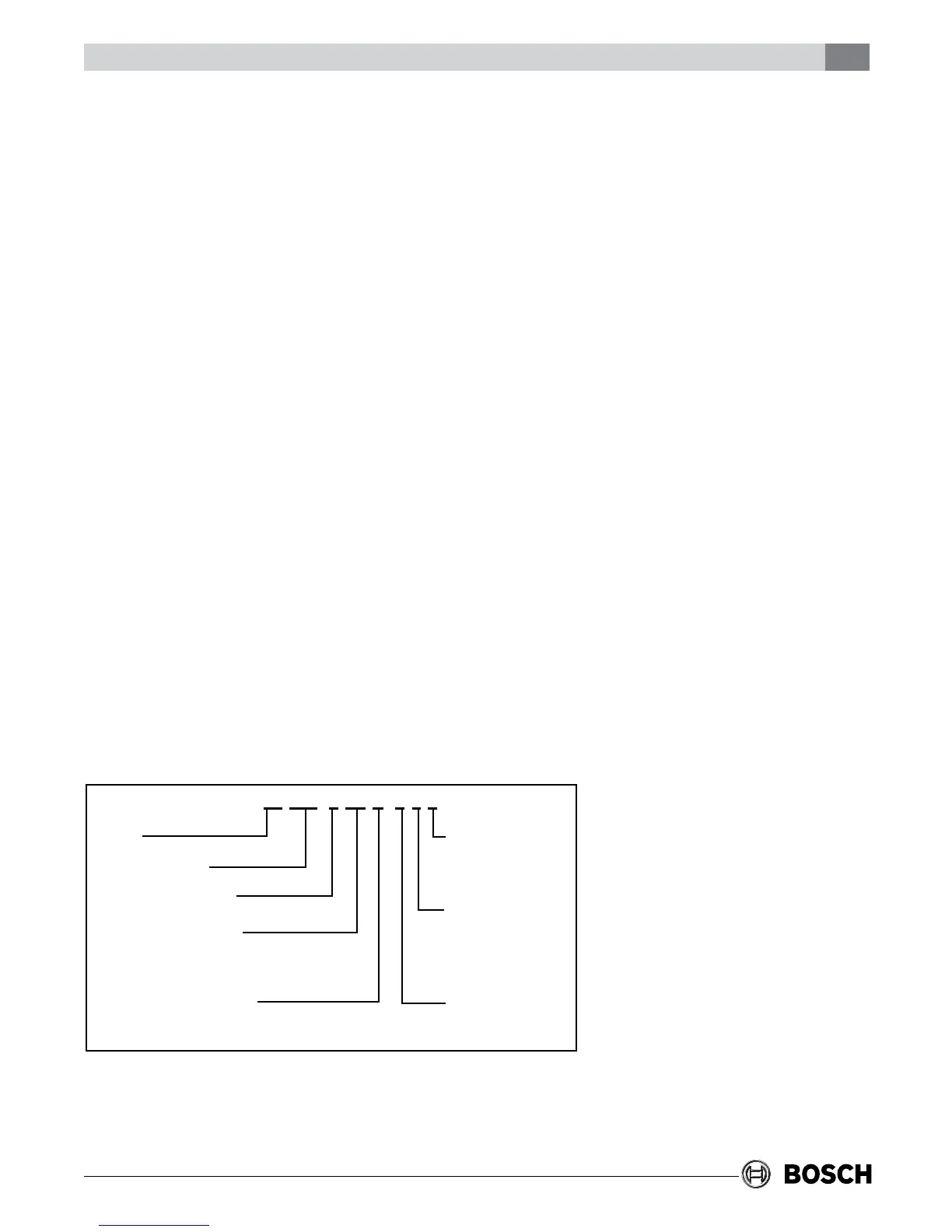
MODEL NOMENCLATURE
SUPPLY AIR LOCATION:
T - TOP (VT ONLY)
E - END BLOW (HZ ONLY)
B - BOTTOM (CF ONLY)
RETURN AIR LOCATION:
S - STRAIGHT THRU
(HZ ONLY)
L - LEFT
R - RIGHT
WATER CONNECTION
LOCATION:
F-FRONT
SERIES:
TA
NOMINAL CAPACITY:
VOLTAGE DESIGNATIONS:
1 - 208/1/60 & 230/1/60
CABINET CONFIGURATION:
VT - VERTICAL
HZ - HORIZONTAL
CF - COUNTERFLOW
HEAT EXCHANGER MATERIAL:
C - COPPER
N - CUPRO-NICKEL
TA 049 - 1 VT C - F L T