6 720 818 731 (2016/07)Tronic 4000 T | Tronic 6000 T
Regulations | 7
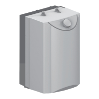
2.8 Appliance layout
Fig. 4 Design of the storage take
(Tronic 6000 T as an example)
[1] Storage cylinder
[2] CFC-free PU insulation
[3] Heating insert
[4] DHW outlet ½ "
[5] Cold water inlet ½ "
[6] Magnesium anode
[7] Temperature control
[8] Isolation fitting
2.9 Wiring diagram
Fig. 5 Connection diagram Tronic 4000 T
Fig. 6 Connection diagram Tronic 6000 T
3Regulations
The applicable local standards regarding the installation and
handling of electrical DHW cylinders must be observed.
4Transport
▶ Do not let the DHW cylinder fall.
▶ Transport the storage tank in the original packaging, and
use suitable means of transportation.
4.1 Transportation, storage and recycling
• The product must be stored in a dry, frost-free location.
• If applicable, observe Directive EU 2012/19/EC for
disposal of electrical and electronic old appliances.
5 Installation
5.1 Important information
Installation, electrical connection and
commissioning may only be carried out by a
contractor approved for such work by the gas or
energy supplier.
CAUTION:
▶ Do not let the DHW cylinder fall.
▶ Only remove the DHW tank from the
packaging at the installation location.
▶ If applicable, the installation of the DHW
cylinder and/or the electrical accessories
must satisfy IEC 60364-7-701.
▶ Select a wall for mounting the cylinder that
has sufficient load bearing capacity to
support the full DHW cylinder. Page 5.
CAUTION: Damage to the heating inserts!
▶ First make the water connections, and then
fill the DHW cylinder.
▶ Then connect the DHW cylinder to the
power supply via a connection socket with a
ground.
 Loading...