6 720 607 800 (2016/02)
Gas regulation | 19
8.2 Pressure regulation
Access to the adjuster screw
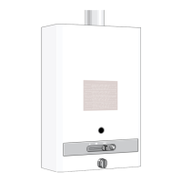
▶ Remove the appliance front cover (see page 16).
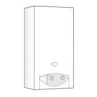
▶ Press both tabs (A) simultaneously and pull the control
box.
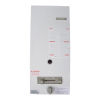
Fig. 17 Remove the control box
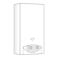
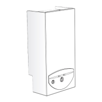
▶ Once the control box is removed, place it as in Fig. 18.
Fig. 18 Control box – gas adjustment position
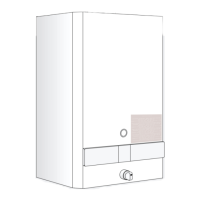
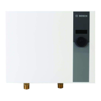
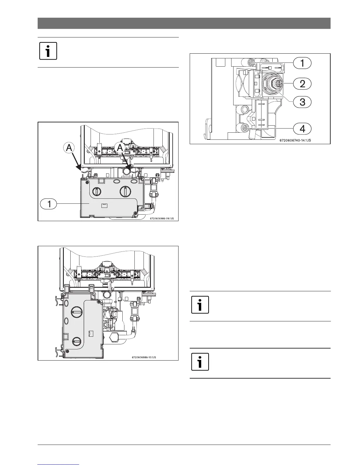
Connection of manometer
▶ Loosen the shutter screw (1).
▶ Connect the U-tube manometer to the burner pressure
measuring point.
Fig. 19 Pressure measuring points
[1] Burner pressure measuring point
[2] Minimum gas flow adjustment screw
[3] Minimum gas flow adjuster
[4] Gas supply pressure measuring point for
Maximum gas flow adjustment
Main switch in position 0.
▶ Set temperature regulator (Fig. 3, [2]) to 60 °C.
▶ Press and hold the burner state key (Fig. 3, [4]) and set
the main switch (Fig. 3, [3]) in position I.
After pressing burner state key for at least 10 seconds, the
appliance is in maximum flow position and the burner state key
flashes.
▶ Open the hot water tap.
▶ Using the adjustor (Fig. 19, [3]) regulate the pressure to
achieve the values indicated in table 14.
Minimum gas flow adjustment
Main switch in position 0.
▶ Set temperature regulator (Fig. 3, [2]) to 35 °C.
▶ Press and hold the burner state key (Fig. 3, [4]) and set
the main switch (Fig. 3, [3]) in position I.
After pressing burner state key for at least 10 seconds, the
appliance is in minimum flow position and the burner state key
flashes.
The selection of the fastest burner pressure
process is recommended.
After regulating, let the appliance operate at
maximum power for at least 30 secs.
Minimum flow adjustment is only necessary
if the burner frequently goes out when the
water flow is reduced.