Do you have a question about the Bose aw-1 and is the answer not in the manual?
Identifies parts with special safety characteristics using symbols or notes.
Procedures for measuring leakage current and insulation resistance to ensure safety.
Use of grounded workstations and wrist straps for handling ESDS devices.
Proper methods for touching, handling, transporting, and storing ESDS devices.
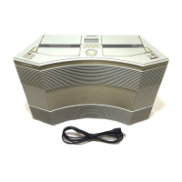
Details size, weight, antenna, case, switching, driver complement, cross over, and cassette format.
Covers amplifier power, quiescent current, output levels, impedance, hum/noise, and voltage/current drains.
Lists FM sensitivity, quieting, signal rejection, and AM rejection.
Details AM sensitivity, image rejection, selectivity, frequency response, and volume sensitivity.
Covers cassette deck response, speed error, wow/flutter, and S/N ratio.
Steps to remove and reinstall the cassette door.
Procedures for removing and replacing the top cover and antenna.
Steps for removing and reinstalling the digital PCB.
Instructions for removing and replacing the control PCB.
Procedures for removing and reinstalling the cassette deck assembly.
Instructions for removing and replacing the cassette deck belts.
Steps to remove the cassette deck motor.
Steps to remove and reinstall the tweeter panel.
Procedures for removing and replacing the tweeter unit.
Instructions for removing and reinstalling the main PCB.
Steps to remove and reinstall the woofer panel.
Procedures for removing and reinstalling the amplifier PCB.
Instructions for removing and replacing the woofer.
Procedures for tuning bias, tracking, and IF alignment for AM.
Procedures for IF alignment for FM.
Steps to adjust the playback/record head azimuth.
Steps to adjust the erase head azimuth.
Procedure to adjust the cassette deck's motor speed.
Steps to adjust the Dolby level for cassette playback.
Procedures for adjusting recording and bias levels for cassette decks.
Illustrates adjustment points RV502, RV501, and connectors P100/J600.
Shows adjustment points for IF and OSC components and connectors.
Illustrates adjustment points for AM antenna, heads, and azimuth screws.
Shows adjustment points RV505 and RV506 on the cassette deck.
Notes regarding part availability, ordering, and critical safety components.
Information on parts used based on unit serial number ranges.
Detailed list of parts for the main assembly with item numbers, descriptions, and notes.
Exploded view diagram illustrating the main assembly components.
Exploded view illustrating chassis, amplifier PCB, and related components.
List of parts specific to the cassette deck assembly with part numbers.
Diagram illustrating the wiring connections for the cassette deck.
Lists resistors by reference designator, description, part number, and notes.
Lists resistors by reference designator, description, part number, and notes.
Lists resistors by reference designator, description, part number, and notes.
Lists resistors by reference designator, description, part number, and notes.
Lists capacitors by reference designator, description, part number, and notes.
Lists capacitors by reference designator, description, part number, and notes.
Lists capacitors by reference designator, description, part number, and notes.
Lists integrated circuits by reference designator, description, and part number.
Lists transistors by reference designator, description, and part number.
Lists diodes by reference designator, description, and part number.
Lists diodes by reference designator, description, and part number.
Lists inductors by reference designator, description, and part number.
Lists transformers, filters, crystals, and miscellaneous components.
Lists fuses, LCD, switches, wiring assemblies, and connectors.
Lists wiring assemblies, connectors, jumpers, and terminals.
Lists chassis, spacers, holders, clamps, and wiring sub-assemblies.
Details for the carton kit and line cord, including quantities and notes.
| Brand | Bose |
|---|---|
| Model | aw-1 |
| Category | Stereo System |
| Language | English |




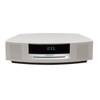

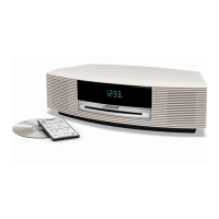
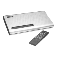
 Loading...