EasyManuals Logo

Bose controlcenter CC-1 User Manual

Bose controlcenter CC-1
28 pages
To Next Page IconTo Next Page
To Previous Page IconTo Previous Page
Page #11 background imageLoading...
Page #11 background image
pro.Bose.com
CC-1 Installation Guide
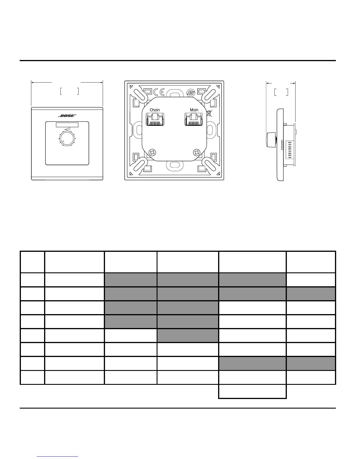
Pin-to-Remote Connections
Connections from the RJ-45 (TIA/EIA 568B wiring) connector on the CC-1 zone controller to
the REMOTE connector on the FreeSpace® amplifier or CONTROL INPUTS connector on the
ControlSpace® processor. Use GPI mode A- in CSD. PowerShare requires a separate wire in the
CAT 5 cable for COM, PWR, and each VOL_# connection.
Pin Color FreeSpace
IZA/ZA
FreeSpace
DXA2120
ControlSpace PowerShare
8 Brown COM
7 White/Brown
6 Green VOL #4 VOL_4
5 White/Blue VOL #3 VOL_3
4 Blue VOL #2 VOL #2 VOL_2
3 White/Green VOL #1 PWR VOL #1 VOL_1
2 Orange PWR #2 VOL_2
1 White/Orange PWR #1 VOL_1 COM PWR
CSD GPI Mode: A-
86 mm sq.
3.4 in sq.
CC-1 Zone Controller - EU
Front View Rear View
DIPON
12345678
34 mm
1. 4 in
Side View
English 11

Questions and Answers:

Question and Answer IconNeed help?

Do you have a question about the Bose controlcenter CC-1 and is the answer not in the manual?

Bose controlcenter CC-1 Specifications

General IconGeneral
BrandBose
Modelcontrolcenter CC-1
CategoryController
LanguageEnglish

Related product manuals