111
TEST PROCEDURE
5. Total Harmonic Distortion + Noise (THD+N) Test
5.1 Apply a balanced 1kHz, +4dBu sine wave to the IN1 analog input.
5.2 Measure the THD+N at the OUT1 output using a 22Hz/22kHz Low Pass Filter and A-weighting. Verify
that the THD+N measures between 0.001% and 0.004%.
5.3 Change the input level to apply a balanced 1kHz, +23.5dBu sine wave to the IN1 analog input.
5.4 Measure the THD+N at the OUT1 output using a 22Hz/22kHz Low Pass Filter and A-weighting. Verify
that the THD+N measures between 0.005% and 0.04%.
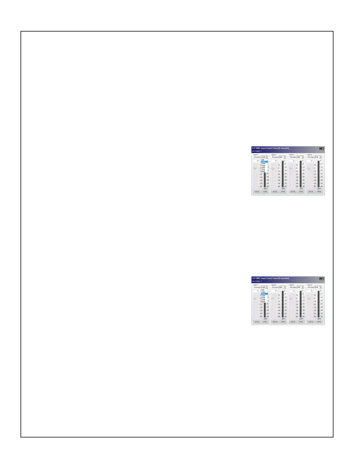
6. Gain (GV=+14dB) Test
6.1 In the CSD window, double-click on the Analog In 1 block to open the
Input Control Panel. Using the pull-down menu, change the pre-gain setting
to +14dB for Inputs 1 - 4. Apply a balanced 1kHz, -10dBu sine wave with a
22Hz/22kHz Low Pass Filter and A-weighting to the IN1 analog input.
6.2 Measure the output level at the OUT1 analog output. Verify that it is
between +2.9dBu and +4.9dBu. Repeat for Inputs 2 - 4.
7. Noise Test
7.1 Set up the unit under test as described in test 6 above. Turn off the signal generator output.
7.2 Measure the output noise at the OUT1 output using a 22Hz/22kHz Low Pass Filter and A-weighting.
Verify that the measured output noise at the OUT1 jack is <-90dBu.
8. Gain (GV=+24dB) Test
8.1 In the CSD window, double-click on the Analog In 1 block to open the
Input Control Panel. Using the pull-down menu, change the pre-gain setting
to +24dB for Inputs 1 - 4. Apply a balanced 1kHz, -20dBu sine wave with a
22Hz/22kHz Low Pass Filter and A-weighting to the IN1 analog input.
8.2 Measure the output level at the OUT1 analog output. Verify that it is
between +2.9dBu and +4.9dBu. Repeat for Inputs 2 - 4.
9. Noise Test
9.1 Set up the unit under test as described in test 8 above. Turn off the signal generator output.
9.2 Measure the output noise at the OUT1 output using a 22Hz/22kHz Low Pass Filter and A-weighting.
Verify that the measured output noise at the OUT1 connector is <-89dBu.
 Loading...