110
TEST PROCEDURE
Analog Input / Output Tests
Perform the following tests to verify proper operation of the analog input and output PCB assemblies.
Notes:
1. Analog Inputs IN9 to IN12 are mapped to outputs OUT5 to OUT8 for the following tests. This is part of
the test setup le.
2. The Automatic Echo Cancellation circuitry will be tested as part of the Analog Input channel 1 tests.
The audio signal is routed through the AEC circuitry using the Parameter 1 setting in the CSD test le.
3. These tests are to be repeated on all 12 analog input channels.
1. Gain (GV=0dB) Test
1.1 Perform the test setup as described at the beginning of the Test Procedures. Open the
ControlSpace
®
Designer (CSD) software. With the EX-1280C_CSD_test_le.csp test design le loaded
and sent to the devices (UUT and USB Dante interface), ensure that you have successfully performed
GO ON-LINE. Once connected, click on the EX-1280C tab in CSD. At the bottom of the screen, you
should see ve yellow parameter buttons. Click on Parameter 1. That parameter setting connects inputs
1 - 4 to outputs 1 - 4. Perform the below tests. Note: If you do not see the Parameter buttons on the
screen, click on the Parameter icon near the right side of the CSD toolbar to display the buttons. You can
hover over the icon to get the name.
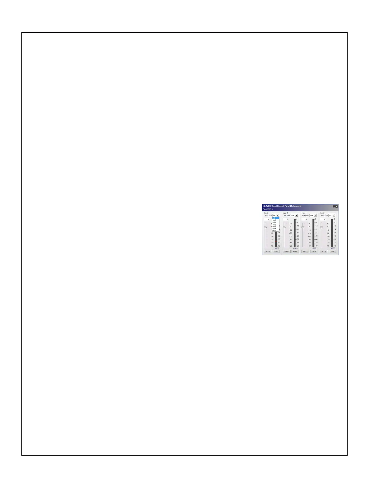
1.2 In the CSD window, double-click on the Analog In 1 block to open the
Input Control Panel. Using the pull-down menu and slider, set the pre-gain to
0dB for Inputs 1 - 4. Close the Input Control Panel. Apply a balanced 1kHz,
+4dBu sine wave with a 22Hz/22kHz Low Pass Filter and A-weighting to the
IN1 analog input.
1.3 Measure the output level at the OUT1 analog output. Verify that it is
between +2.9dBu and +4.9dBu. Repeat for Inputs 2 - 4.
2. Noise Test
2.1 Set up the unit under test as described in test 1 above. Turn off the signal generator output.
2.2 Measure the output noise at the OUT1 output using a 22Hz/22kHz Low Pass Filter and A-weighting.
Verify that the measured output noise at the OUT1 connector is <-91dBu.
3. Frequency Response 20kHz Test
3.1 Apply a balanced 20kHz, +4dBu sine wave with a 22Hz/22kHz Low Pass Filter and A-weighting to
the IN1 analog input.
3.2 Measure the output level at the OUT1 analog output. Verify that it is between between +2.9dBu and
+4.9dBu.
4. Frequency Response 20Hz Test
4.1 Apply a balanced 20Hz, +4dBu sine wave with a 22Hz/22kHz Low Pass Filter and A-weighting to the
IN1 analog input.
4.2 Measure the output level at the OUT1 analog output. Verify that it is between +2.9dBu and +4.9dBu.
 Loading...