12
Disassembly Procedure
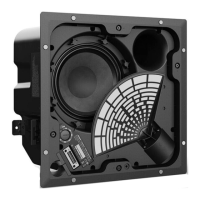
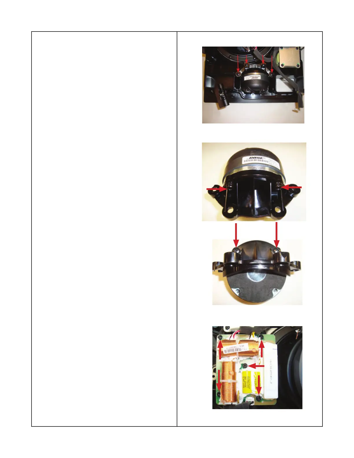
4. Removal of the driver fl ange
4.1 Remove the two screws indicated by the
red arrows in fi gures 18 and 19. The driver
fl ange will be reused and not supplied as a
service part.
Figure 18
Figure 19
5. Crossover Removal
5.1 Perform procedure 1 and 2.
5.2 Remove the fi ve T20 Torx screws that
secure the crossover assembly to the baffl e
as shown in fi gure 20.
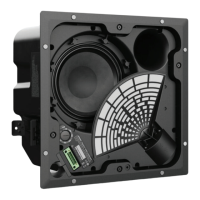
Figure 17
Figure 20
3.4 Remove the four screws indicated by
the red arrows as shown in fi gure 17. The
driver and driver fl ange will come off as an
assembly.
Note: During remounting of the driver fl ange
to the baffl e, do not tighten the six screws
until all are threaded in position, then tighten,
as there is a possibility of cross threading one
of the screws.
 Loading...