13
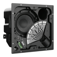
5.3 Remove the input connector from the
crossover as indicated by the red arrow in
Figure 21.
Figure 21
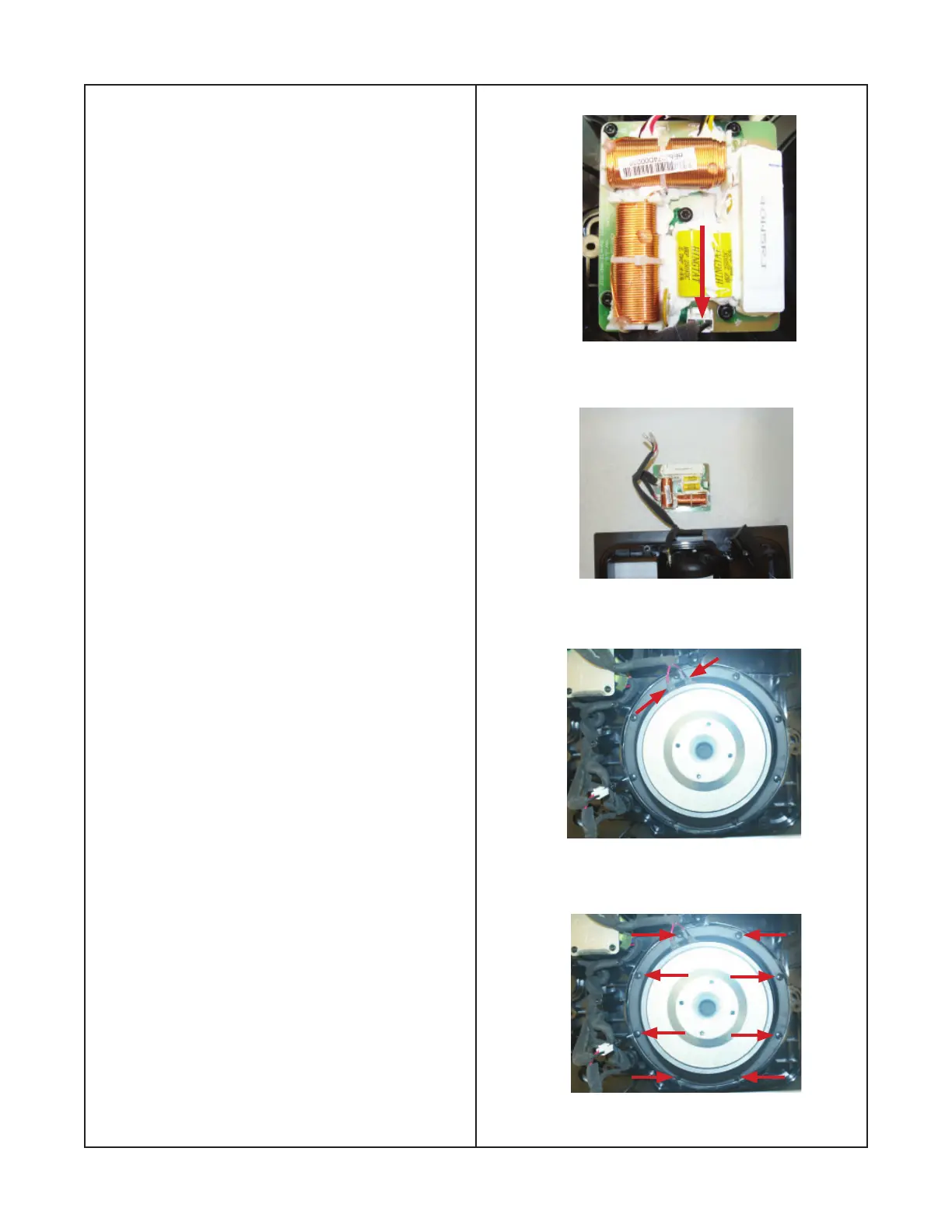
Figure 22
Figure 23
Figure 24
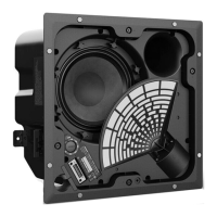
6.3 Remove the eight screws that secure
the woofer to the baffl e as shown in fi gure
24. Carefully remove the woofer.
Disassembly Procedure
6.2 Remove the positive and negative wires
from the woofer as shown in fi gure 23.
Note: The crossover can be placed off to the
side as shown in fi gure 22.
6. Woofer Removal
6.1 Perform procedure 5 to remove the
crossover. The crossover must be removed
to access the woofer screws.
 Loading...