2
Table of Contents
Warranty..........................................................................................................................2
Product Description.............................................................................................................................. 3
Specifications......................................................................................................................4
Part List Notes.......................................................................................................................................4
Packaging Parts List...........................................................................................................................5
Figure 1. Packaging View...................................................................................................................5
Main Assembly Parts List...................................................................................................................6
Figure 2. Exploded View.....................................................................................................................6
Schematic and Connector Diagrams..............................................................................................7-8
Figure 3. Schematic diagram EM90...................................................................................................7
Figure 4. Schematic diagram EM180.................................................................................................7
Figure 5. Connector diagrams.............................................................................................................8
Disassembly Procedures...................................................................................................................9
Figures 6 thru 13.............................................................................................................................9-11
Driver Removal..................................................................................................................................11
Figures 14 thru 17...... .....................................................................................................................11-12
Driver Flange Removal......................................................................................................................12
Figures 18 thru 19................................................................................................................................12
Crossover Removal..........................................................................................................................12
Figures 20 thru 22..........................................................................................................................12-13
Woofer Removal................................................................................................................................13
Figures 23 thru 24...............................................................................................................................13
Transformer and Switch Assembly ................................................................................................14
Figures 25 thru 32..........................................................................................................................14-15
Enclosure and Baffl e Gaskets..........................................................................................................16
Figures 33 thru 35...............................................................................................................................16
Test Procedures.................................................................................................................................17
Service Manual Revision History.....................................................................................................18
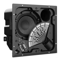
CAUTION: The Bose
®
EdgeMax
®
Loud Speaker contains no user-serviceable parts.
To prevent warranty infractions, refer servicing to warranty service stations or factory
service.
WARRANTY
The Bose EdgeMax Loud Speaker is covered by a limited 5-year warranty.
PROPRIETARY INFORMATION
THIS DOCUMENT CONTAINS PROPRIETARY INFORMATION OF
BOSE CORPORATION WHICH IS BEING FURNISHED ONLY FOR
THE PURPOSE OF SERVICING THE IDENTIFIED BOSE PRODUCT
BY AN AUTHORIZED BOSE SERVICE CENTER AND SHALL NOT BE
REPRODUCED OR USED FOR ANY OTHER PURPOSE.
 Loading...