11
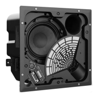
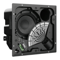
2.6 Carefully lift off the baffl e from the enclo-
sure, taking care not to damage the baffl e or
internal components as shown in fi gure 13.
Figure 13
3. Driver Removal
3.1 Refer to the disassembly procedures,
see above.
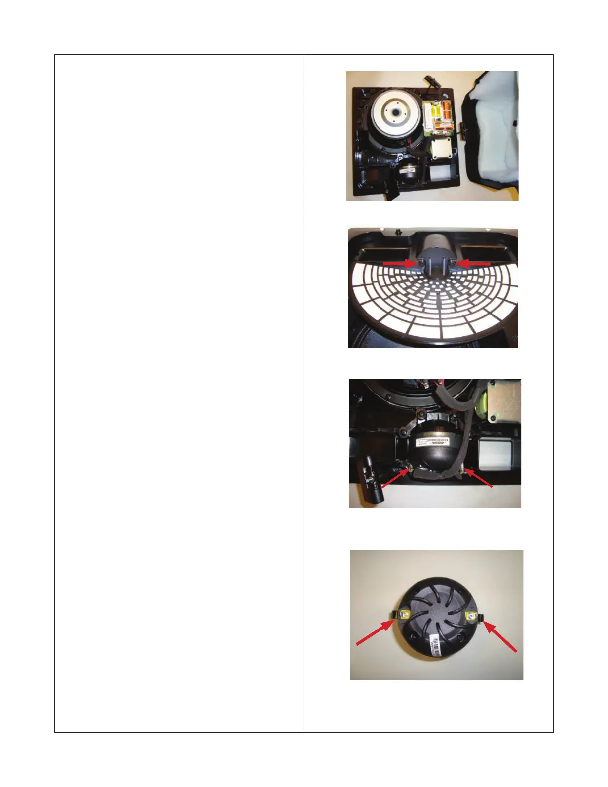
3.2 Remove the two screws indicated by the
red arrows shown in fi gure 14. These screws
secure the front of the driver fl ange bracket
to the baffl e.
Figure 14
Figure 15
3.3 Remove the negative and positive wires
from the driver terminals as indicated by
red arrows shown in fi gures 15 and 16. The
negative terminal is smaller than the positive
terminal. When the driver is mounted to
the baffl e, the negative terminal should be
located on the left and the positive terminal
will be located on the right as shown in
Figure 16.
Figure 16
Neg
Pos
Disassembly Procedure
 Loading...